Page 1103 - Foton Workshop Manual - Tunland (AT)
P. 1103

DIAGNOSTICS - ASSEMBLY INSTRUMENT                           04-957

                 Diagnostic step

                 1 .    Check the CAN communication line.

                 (a)    Ignition Switch:ON.

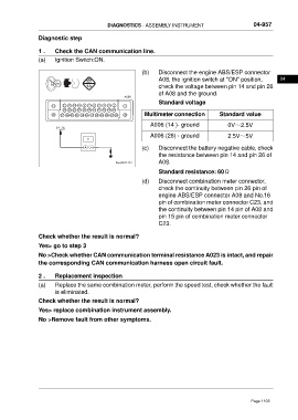
                                                           (b)    Disconnect the engine ABS/ESP connector
                                                                  A08, the ignition switch at "ON" position,         04
                                                                  check the voltage between pin 14 and pin 26
                                                                  of A08 and the ground.
                                                    A006
                                                                  Standard voltage
                      13   12  11  10  9  8  7  6  5  4  3  2  1
                           24  23  22  21  20 19  18  17 16  15  14
                      38  37  36  35  34  33  32  31  30  29  28  27  26  25  Multimeter connection  Standard value
                                                               A006 (14 )- ground              0V~2.5V
                        14 26
                                                               A006 (26) - ground              2.5V~5V

                                                           (c)    Disconnect the battery negative cable, check
                                                                  the resistance between pin 14 and pin 26 of
                                                 ftwxd041451      A08.
                                                                  Standard resistance: 60Ω

                                                           (d)    Disconnect combination meter connector,
                                                                  check the continuity between pin 26 pin of
                                                                  engine ABS/ESP connector A08 and No.16
                                                                  pin of combination meter connector C23, and
                                                                  the continuity between pin 14 pin of A08 and
                                                                  pin 15 pin of combination meter connector
                                                                  C23.


                 Check whether the result is normal?
                 Yes> go to step 3

                 No >Check whether CAN communication terminal resistance A023 is intact, and repair
                 the corresponding CAN communication harness open circuit fault.

                 2 .    Replacement inspection
                 (a)    Replace the same combination meter, perform the speed test, check whether the fault
                        is eliminated.
                 Check whether the result is normal?

                 Yes> replace combination instrument assembly.
                 No >Remove fault from other symptoms.


                                                                                                        Page 1103
   1098   1099   1100   1101   1102   1103   1104   1105   1106   1107   1108