
Page 1679 - Foton Workshop Manual - Tunland (AT)
P. 1679
AXLE AND PROPELLER SHAFT - FRONT DIFFERENTIAL ASSEMBLY 34-19
CHECK & AFJUSTMENT
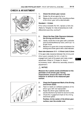
1 . Check the driven gear runout.
(a) Rotate the driven gear by hand.
(b) Measure the runout on the mounting surface
of the driven gear with a dial indicator.
Standard: ≤0.2mm
If the runout exceeds the limit, replace a new one.
(Refer to "Chapter 34. Axle & transmission shaft -
differential assembly, overhaul")
2 . Check the Gear Side Clearance between
the Driving and Driven Gears
(a) Gently rotate the driven gear both clockwise
and counterclockwise by hand, until it can no
longer move.
(b) Measure the gear side clearance between the
driving and driven gears with a dial indicator.
Gear side clearance: 0.11~0.16mm Limit: 0.2mm
If the gear side clearance between the driving and
driven gears exceeds the limit, check the
engagement mark of the gears and make proper
34
adjustment. (Refer to "Chapter 34. Axle &
transmission shaft - differential assembly, check &
adjustment")
NOTICE
Measure the 4 points evenly distributed on the
perimeter of the driven gear. During
measurement, ensure the head of the dial
indicator is vertical to the measured gear
surface.
3 . Check the Engagement Mark of the Driving
and Driven Gears
(a) Paint 3-4 teeth at 3 different positions of the
driven gear with red lead powder.
(b) Roate the driven gear clockwise and
counterclockwise by hand for several rounds.
(c) Check the engagement mark of the driving
and driven gears.
Position: At the center of the driven gear
surface, near the smaller end.
Page 1679