
Page 2271 - Foton Workshop Manual - Tunland (AT)
P. 2271
WIRING - SYSTEM CIRCUIT DIAGRAM 71-69
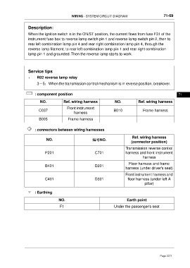
Description:
When the ignition switch is in the ON/ST position, the current flows from fuse F31 of the
instrument fuse box to reverse lamp switch pin 1 and reverse lamp switch pin 2, then to
rear left combination lamp pin 4 and rear right combination lamp pin 4, through the
reverse lamp filament, to rear left combination lamp pin 1 and rear right combination
lamp pin 1 and grounded. Then the reverse lamp starts to work.
Service tips
• R02 reverse lamp relay
3-5:When the transmission control mechanism is in reverse position, breakover.
: component position 71
NO. Ref. wiring harness NO. Ref. wiring harness
Front instrument
C037 B010 Frame harness
harness
B005 Frame harness
: connectors between wiring harnesses
Ref. wiring harness
NO. 编号NO.
(connector position)
Transmission reverse control
P201 C701 harness and front instrument
harness
Floor harness and frame
B401 D201
harness (under driver's seat)
Front instrument harness and
C401 D301 floor harness (under left A
pillar)
: Earthing
NO. Earth point
F1 Under the passenger's seat
Page 2271