
Page 2268 - Foton Workshop Manual - Tunland (AT)
P. 2268
71-66 WIRING - SYSTEM CIRCUIT DIAGRAM
Description:
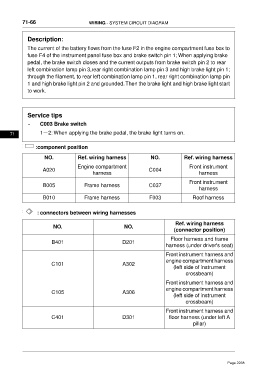
The current of the battery flows from the fuse F2 in the engine compartment fuse box to
fuse F4 of the instrument panel fuse box and brake switch pin 1; When applying brake
pedal, the brake switch closes and the current outputs from brake switch pin 2 to rear
left combination lamp pin 3,rear right combination lamp pin 3 and high brake light pin 1;
through the filament, to rear left combination lamp pin 1, rear right combination lamp pin
1 and high brake light pin 2 and grounded.Then the brake light and high brake light start
to work.
Service tips
• C003 Brake switch
71 1-2: When applying the brake pedal, the brake light turns on.
:component position
NO. Ref. wiring harness NO. Ref. wiring harness
Engine compartment Front instrument
A020 C004
harness harness
Front instrument
B005 Frame harness C037
harness
B010 Frame harness F003 Roof harness
: connectors between wiring harnesses
Ref. wiring harness
NO. NO.
(connector position)
Floor harness and frame
B401 D201
harness (under driver's seat)
Front instrument harness and
engine compartment harness
C101 A302
(left side of instrument
crossbeam)
Front instrument harness and
engine compartment harness
C105 A306
(left side of instrument
crossbeam)
Front instrument harness and
C401 D301 floor harness (under left A
pillar)
Page 2268