
Page 7 - POWERGEN E-Brochure
P. 7
VERIFIABLE ENERGY SAVINGS
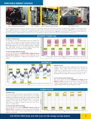
Figure 1. TIS Testing w/ Data Logging Meters Figure 2. XL Subpanel Figure 3. Isolation Xfmr with 3 Test Probes Figure 4. 500 HP DC Motor
TIS performance graphs below show real-time results when (3) XL Modules are turned ON and OFF when connected to a 500 HP Motor. Figure 1 shows meter recording
station. Figure 2 shows (3) XL-3D-480V modules connected to a subpanel which connects in parallel to Motor Drive (not shown). Figure 3 shows CT and voltage meter
test probes connected to main conductors in an Isolation Transformer on the line side of Motor Drive. Figure 4 shows 500 HP Motor. XL Subpanel and XL modules are
located 20’ upstream of 500 HP Motor and 200’ downstream of the 500A main breaker located in Main Distribution Panel (MDP) in electrical room.
APPARENT POWER (VA) GRAPH #5 - APPARENT POWER (VA)
RECORDING @ 500 HP DC MOTOR FOR TIS TEST OF (3) XL UNITS @ 500HP DC MOTOR
1/10/2014 11:20:02 AM - 1/10/2014 12:15:02 PM
APPARENT POWER (kVA) 3 3353,50,00000 XULSEOS OFFFF XULSEOS OFFFF XULSEOS OFFFF XULSEOS OFFFF XULSEOS OFFFF
The product of the root-mean-square (rms) of Voltage and
Current. When impedance is pure resistance, Apparent Power 3 3303,00,00000
equals Real Power (kW). But when reactance (inductive loads
like motors) exists on the circuit, Apparent Power is greater 3 2352,50,00000
than Real Power because it contains kVAR demand from
inductive loads requiring Reactive Power (kVAR). 3 2302,00,00000
TIS TEST RESULTS (500 HP MOTOR)
Test results show an average REDUCTION in Apparent Power 31 531,50,00000
of 60.8 kVA or 19.3%. XL Systems reduce Apparent Power
(kVA) which corresponds to reductions in Reactive Demand 31 031,00,00000
(kVAR).
V 3 0350,50,00000 XULSESOONN XULSESOONN XULSEOS ONN XULSEOS ONN XULSEOS ONN XULSEOS ONN
V 3 0300,00,00000
2 9259,50,00000
Power Factor VA 2 9209,00,00000
Power Factor VA2 8258,50,00000
2 8208,00,00000
2 7257,50,00000
2 7207,00,00000
2 6256,50,00000
2 6206,00,00000
2 5255,50,00000
2 5205,00,00000
2 4254,50,00000
111:215::020 A5MAM 111:130::030 A0MAM 111:315::030 A5MAM 111:140::040 A0MAM 111:145::040 A5MAM 111:150::050 0AMAM 1111:55::5005AMAM 1122:00::0000PMPM 1122:05::0005PMPM 1122:10::0000PMPM 1122:1:51:005PMPM
TimeTime
?????? Apparent Pow er Total (316645.13 VA, min:240304.09 VA; max:335559.78 VA; avg:283236.31 VA)
GRAPH #1 - VOLTAGE (V) VOLTAGE (V)
4 8 3483 RECORDING @ 500 HP DC MOTOR FOR TIS TEST OF (3) XL UNITS @ 500HP DC MOTOR XULSESOONN XULSESOONN VOLTAGE (Volts)
4 8 2482 1/10/2014 11:20:02 AM - 1/10/2014 12:15:02 PM Voltage is the measurement of electromotive force (EMF) or
4 8 1481 potential, which makes electrons ?ow in AC circuits and
4 8 0480 XULSESOONN conductors. Transmitting power is done more e?ciently at
4 7 9479 higher voltages because power is lost according to current
4 7 8478 XULSEOS ONN XULSESOONN XULSESOONN squared times the resistance it has to pass through (I2*R).
4 7 7477 TIS TEST RESULTS (500 HP MOTOR)
4 7 6476 XULSEOS OFFFF XULSEOS OFFFF Test results show an average INCREASE in Voltage of 3.5
4 7 5475 VOLTS or 0.73%. XL Systems decrease current and increase
4 7 4474 XULSEOS OFFFF XULSEOS OFFFF XULSESOOFFFF voltage through magnetic chokes, step-up transformers and
4 7 3473 magnetic phase balancing of voltage and current.
4 7 2472
4 7 1471
4 7 0470
4 6 9469
4 6 8468
4 6 7467
4 6 6466
Time111:125::020 A5MAM 111:130::030 0AMAM 111:135::030 A5MAM 111:140::040 A0MAM 111:145::040 A5MATMime 111:150::050 0AMAM 1111:55::5005AMAM 1122:00::0000PMPM 1122:05::0005PMPM 1122:10::0000PMPM 1122:1:51:005PMPM
?????? RMS Voltage Ø12 (480.18 V, min:469.62 V; max:483.31 V; avg:476.51 V) ?????? RMS Voltage Ø32 (475.05 V, min:465.05 V; max:478.03 V; avg:471.81 V) ?????? RMS Voltage Ø31 (478.62 V, min:468.87 V; max:482.47 V; avg:475.66 V)
POWER FACTOR GRAPH #6 - POWER FACTOR
RECORDING @ 500 HP DC MOTOR FOR TIS TEST OF (3) XL UNITS @ 500HP DC MOTOR
1/10/2014 11:20:02 AM - 1/10/2014 12:15:02 PM
POWER FACTOR 0 . 6-90.5695 XULSESOOFFFF XULSEOS OFFFF XLUSOESFOFFF XULSEOS OFFFF XULSEOS OFFFF
The ratio of Real Power (Watts) to Apparent Power (VA). When 0 . 7 0-0.7
current and voltage are in phase, power factor is 1. As circuit 0 . 7-00.5705 XULSESOONN XULSEOS ONN XULSEOS ONN XULSEOS ONN XULSESOONN XULSESOONN
inductive loads (motors) retard the current waveform it falls 0 . 7-10.71
out of phase and lags the voltage waveform. If current lags 0 . 7-10.5715
voltage by 10%, power factor is 90% or 0.90. As magnetic 0 . 7-20.72
?elds build up, it takes more time for current to reach its full 0 . 7-20.5725
value in inductive loads. 0 . 7-30.73
TIS TEST RESULTS (500 HP MOTOR) 0 . 7-30.5735
Test results show an average INCREASE in Power Factor of 0 . 7-40.74
0.132 or 18.7%. XL Systems improve power factor through the 0 . 7-40.5745
magnetic chokes which increase energy e?ciency in inductive 0 . 7-50.75
loads such as motors. 0 . 7-50.5755
0 . 7-60.76
0 . 7-60.5765
0 . 7-70.77
0 . 7-70.5775
0 . 7-80.78
0 . 7-80.5785
0 . 7-90.79
0 . 7-90.5795
0 . 8 0-0.8
0 . 8-00.5805
0 . 8-10.81
0 . 8-10.5815
0 . 8-20.82
0 . 8-20.5825
0 . 8-30.83
0 . 8-30.5835
0 . 8-40.84
111:125::020 5AMAM 1111:30::0300AMAM 111:135::030 5AMAM 1111:40::0400AMAM 1111:45::0405AMAM 1111:50::5000AMAM 1111:5:55:005AMAM 1122:0:00:000PMPM 1122:0:50:005PMPM 1122:10::0000PMPM 1122:1:51:005PMPM
TimeTime
?????? True Pow er Factor Total (0.83i, min:0.84i; max:0.69i; avg:0.77i)
Call 440-941-0250 today and start your no-risk energy savings project 7