
Page 3048 - Flipbook_SolidDesignSoutheast2020
P. 3048
DESIGN FACTORS
Sale Technical Sheet
69 William Street, Belleville, NJ 07109 STS Number ________
PH: 973-759-4600 * Fax: 973-759-6449 Effective Date _______
EMAIL: info@vac-u-max.com Supersedes _________
WEB SITE: www.vac-u-max.com
If the system cannot achieve its rated duty, determine whether the problem is due to product feeding,
pipeline or air supply. Check on the conveying line pressure drop. If it is below the air mover’s capabil-
ity, product feed into the pipeline may be insufficient. If the maximum output of the feeder does not meet
the conveying capability of the pipeline, however, it will probably be necessary to fit a larger feeder.
Before recommending a larger feeder, be sure that air leakage isn’t the real culprit. Check rotary valves
in particular, as well as air vents and clearances on all moving parts. Don’t forget to check the filtration
unit. If it has been incorrectly sized, pressure drop across the filter may be too high. Also check that the
filter cloths don’t need replacing or cleaning. It may be that an additional or a larger filter is needed. If
these modifications don’t bring the system to rated output, an air mover with a higher pressure rating or
an increase in pipeline bore are indicated, but be sure to consider how this will influence other parts of
the system.
Reducing air flow Rate
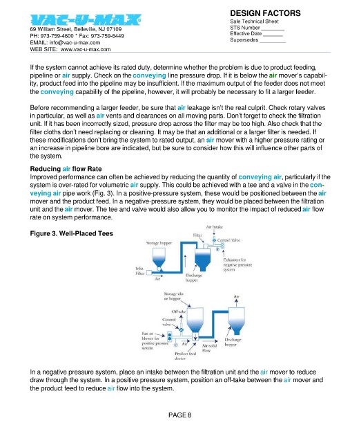
Improved performance can often be achieved by reducing the quantity of conveying air, particularly if the
system is over-rated for volumetric air supply. This could be achieved with a tee and a valve in the con-
veying air pipe work (Fig. 3). In a positive-pressure system, these would be positioned between the air
mover and the product feed. In a negative-pressure system, they would be placed between the filtration
unit and the air mover. The tee and valve would also allow you to monitor the impact of reduced air flow
rate on system performance.
Figure 3. Well-Placed Tees
In a negative pressure system, place an intake between the filtration unit and the air mover to reduce
draw through the system. In a positive pressure system, position an off-take between the air mover and
the product feed to reduce air flow into the system.
PAGE 8