
Page 291 - Divyank Tyagi
P. 291
|
eXportIng 2D CaD Data 257
In the following exercise, you will continue to use the c07-Sample-Building-Start.rvt
project file while utilizing the saved list of views you created in the “Preparing for CAD Exports”
exercise.
1. From the Application menu, click Export ➢ CAD Formats ➢ DWG. In the DWG Export
dialog box, make sure Export Set is selected in the Export drop-down. Click the Modify
Export Setup ellipsis button (three dots) at the top of the dialog box.
2. In the Modify DWG/DXF Export Setup dialog box, select the New button from the bottom
left to create a new export setup. Name the new export setup British Plans with Phase.
3. In the Layers tab, set the Export Layer Options drop-down list to Export Category
Properties BYLAYER And Overrides BYENTITY. Locate the Load Layers From Standards
drop-down list and select British Standard 1192. You will receive an error message stating
that loading these settings will replace your previous settings. Click Yes to accept.
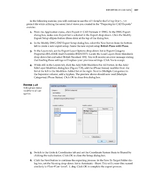
4. While still in the Layers tab, click the Add/Edit Modifiers For All button. In the Add/
Edit Layer Modifiers dialog box (Figure 7.28), add the {Phase Status} modifier from the
list at the left to the Modifiers Added list at the right. Next to {Multiple Categories} in
the Separator column, add a hyphen. The preview above should now read {Multiple
Categories}-{Phase Status}. Click OK to close this dialog box.
Figure 7.28
add a phase status
modifier to all cat-
egories.
5. Switch to the Units & Coordinates tab and set the Coordinate System Basis to Shared by
clicking the radio button. Click OK to close the Setup dialog box.
6. Click the Next button to continue the exporting process. In the Save To Target Folder dia-
log box, set the Naming drop-down list to Automatic - Short. This will create files named
similarly to FloorPlan-Level 1.dwg. Click OK to complete the export process.
c07.indd 257 5/3/2014 10:49:00 AM