
Page 286 - Divyank Tyagi
P. 286
252 | ChaptEr 7 InteroperabIlIty: WorkIng MultIplatforM
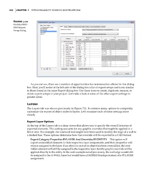
Figure 7.21
Modify DWg/
DXf export
setup dialog
As you can see, there are a number of opportunities for customization offered in this dialog
box. First, you’ll notice at the left side of the dialog box a list of export setups and icons similar
to those found in the main Export dialog box. Use these icons to create, duplicate, rename, or
delete export setups in your project. Let’s take a look at some of the other export settings in
greater detail.
Layers
The Layers tab was shown previously in Figure 7.21. It contains many options to completely
customize the export of object styles to layers. Let’s examine each of these settings more
closely.
Export Layer Options
At the top of the Layers tab is a drop-down that allows you to specify the overall behavior of
exported elements. This setting accounts for any graphic overrides that might be applied in a
Revit view. For example, the Linework tool might have been used to modify the edge of a wall to
a dashed line. These options determine how that override will be exported to a CAD format.
Export Category Properties BYLAYER And Overrides BYENTITY This option will
export unmodified elements to their respective layer assignments, and their properties will
remain assigned to the layer. If an object or part of an object has been overridden, the over-
ridden element will still be assigned to the respective layer, but the graphic override will be
applied directly to the entity. In the wall example noted previously, the wall edge would still
be assigned to the A-WALL layer but would have a DASHED linetype instead of a BYLAYER
assignment.
c07.indd 252 5/3/2014 10:48:59 AM