
Page 338 - Divyank Tyagi
P. 338
304 | ChAPter 8 AdvAnced Modeling And MAssing
Creating a Generic Model Mass Family
Although it’s possible to create complex forms as a generic model in the Family Editor, they
do not behave as masses when you place them in the project. You can assign standard walls,
curtain walls, and roofs to the faces, but you can’t add patterns, create mass floors, or even
schedule the results as a mass. The tools you will use in this exercise are the tools available for
building most other 3D content using extrusions, sweeps, and blends. It’s good to understand
how to use these tools so you’re familiar with all the types of modeling in Revit software.
1. Open a Generic Model template by choosing the Application button ➢ New ➢ Family.
Select either Generic Model.rft or Metric Generic Model.rft from the list of default
templates.
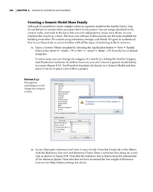
In some cases, you can change the category of a family by clicking the Family Category
and Parameters button in the ribbon; however, you can’t convert a generic model family
to a mass (Figure 8.57). You’ll need to maintain the family as a Generic Model and then
place it into an in-place mass within a project.
Figure 8.57
Message box
explaining you can’t
change the category
to Mass
2. Go to a floor plan reference-level view in your family. From the Create tab in the ribbon,
click the Reference Line tool (not Reference Plane). Draw a reference line along the y-axis
(up), as shown in Figure 8.58. Note that the reference line is drawn from the intersection
of the reference planes. Note also that we have increased the line weight of Reference
Lines in the Object Styles settings for clarity.
c08.indd 304 05-05-2014 16:47:46