
Page 512 - Divyank Tyagi
P. 512
478 | ChaPTER 12 Creating Walls and Curtain Walls
The Coarse Scale Fill Pattern type property (along with Coarse Scale Fill Color) defines a fill
pattern to be applied to the wall type when a view’s Detail Level is set to Coarse. These settings
are an important tool to help you communicate your designs more effectively. For example, you
might want to set all the fire-rated wall types to display with a red solid fill for coarse views.
Using these type properties for walls is a slightly different approach than you might use for
design plans in which you want all wall types to display with a black solid fill. For the design
plan approach, you can override the fill pattern for the Walls category in the Visibility/Graphic
Overrides dialog box for a view or a view template.
When the Detail Level property of a view is set to Medium or Fine, the individual layers of
a wall type’s structure are visible—including any fill patterns that are assigned to the materials
in the wall structure (you’ll learn more about wall structure in the next section of this chapter).
When the Detail Level is set to Coarse, the wall type is displayed only with the pattern defined in
the Coarse Scale Fill Pattern parameter—if one is defined. This property is best explored with the
generic masonry wall types in the default project templates.
Create a new project with any Autodesk default project template, and then place a wall
segment using the type Generic - 8ʺ Masonry (Generic - 225 mm Masonry) in a plan view that is
set to Coarse. You will see that a fill pattern is displayed. What you are seeing is the fill pattern
that is assigned to the Coarse Scale Fill Pattern type property of the wall—not the pattern that
is assigned to the material within the wall structure. Select the generic wall segment you just
created, and in the Properties palette click Edit Type. Change the Coarse Scale Fill Pattern to No
Pattern, and then click OK to close all open dialog boxes. No fill pattern will appear for this wall
type in a coarse view. From the view control bar, set the Detail Level to Medium, and you will
then see the fill pattern as it is defined in the material within the wall structure.
Editing Wall Structures
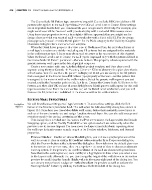
Certification We will first discuss editing a wall type’s structure. To access these settings, click the Edit
Objective button in the Structure parameter field. This will open the Edit Assembly dialog box, shown in
Figure 12.3. From here you can add or delete wall layers, define their materials, move layers in
and out of the core boundaries, and assign functions to each layer. You can also add sweeps and
reveals or modify the vertical constraints of the layers.
This dialog box is divided into four zones: the Preview window, the Layers table, the Default
Wrapping option, and the Modify Vertical Structure options (which are active only when the
preview is set to section display). The area above the Layers zone holds basic reporting about
the wall type: its family name, sample height in the Preview window, thickness, and thermal
properties.
Preview Window On the left side of the dialog box, you will see a graphic preview of the
wall structure in plan or section. If you didn’t activate it in the Type Properties dialog box,
click the Preview button at the bottom of the dialog box. To switch from the default plan view
to the section view or vice versa, click the drop-down list next to View to choose an alternate
viewing option. In the preview, the core boundaries of the wall are shown with green lines.
Note that in the section preview, each wall layer is highlighted in blue when you select a row
in the Layers table. Also note that you can change the height of the wall shown in the section
preview by modifying the Sample Height value in the upper-right part of the dialog box. You
can use any mouse-based navigation method to adjust the preview as well as activate the
®
SteeringWheels feature by clicking the button at the bottom left of the dialog box.
c12.indd 478 5/3/2014 11:12:29 AM