
Page 517 - Divyank Tyagi
P. 517
|
using extended Modeling teChniques for BasiC Walls 483
Creating Layer Wrapping
To create a layer-wrapping solution for openings that reflect real-world conditions, you must
define two settings. First, select the layer(s) of the wall structure you want to wrap and check
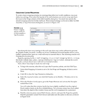
the boxes in the Wraps column of the Edit Assembly dialog box. You must then specify the
default wrapping behavior for the wall type. These default settings can be set in either the Edit
Assembly or Type Parameters dialog box, as shown in Figure 12.9.
Figure 12.9
default wrapping
options can be set
in edit assembly or
type Parameters.
Specifying the layer wrap settings in the wall type alone may not be sufficient to generate
the graphic results you desire. Another set of rules established in hosted families allows you to
further customize how layers in a wall will wrap to inserted objects. The following exercise will
illustrate this functionality.
Begin by opening the file c1-Wall-Wrapping.rvt or c12-Wall-Wrapping-Metric.rvt from
this book’s website: www.sybex.com/go/2015masteringrevit2015. Activate the Level 1
floor plan, and you should see a wall with an inserted window.
Next, follow these steps to create the wall wrap:
1. To begin the exercise, select the wall, open the Properties palette, and click Edit Type.
Notice that Wrapping At Inserts is set to Do Not Wrap and Wrapping At Ends is set to
None.
2. Click OK to close the Type Parameters dialog box.
3. Select the inserted window and click Edit Family on the Modify | Windows tab in the
ribbon.
4. When the Window family opens, go to the Project Browser and activate the floor plan
named Floor Line.
You will notice that this window family has been slightly modified from the original
Fixed window family in the Revit default library. Two reference planes have been added
that allow the depth of the window frame and the wall wrapping to be customized.
5. Find the reference plane named Wall Closure, select it, and open the Properties palette.
Find the parameter named Wall Closure and make sure the option is checked, as shown
in Figure 12.10.
c12.indd 483 5/3/2014 11:12:32 AM