
Page 520 - Divyank Tyagi
P. 520
486 | ChaPTER 12 Creating Walls and Curtain Walls
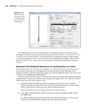
Figure 12.12
With the section
view active, tools
for modifying the
vertical structure
become active.
In the following sections, we’ll examine how to create these types of articulation in your
wall type. To begin the exercises, download and open the file c12-Wall-Articulation.rvt or
c12-Wall-Articulation-Metric.rvt from this book’s companion web page at www.sybex
.com/go/2015masteringrevit2015. There are two samples of the Exterior - Brick on Mtl.
Stud wall type. You will create a new wall type based on this wall throughout the following
exercises.
assigning Two Different Materials on the Finish Face of a Wall
We will begin our series of exercises by creating a new wall type based on an existing layered
wall structure. Select the two wall segments in the exercise file and click Edit Type in the
Properties palette. In the Type Properties dialog box, click the Duplicate button and create a new
wall type named Mastering - Wall Exercise.
Now let’s assume that you need to create a partial region of the finish face where the material
is different but is of the same thickness. For example, you might want to use a split-face concrete
block at the base of the wall instead of brick:
1. Activate the default 3D view and select one segment of wall in the view. From the
Properties palette, click Edit Type, and in the Type Properties dialog box, click the Edit
button in the Structure field to open the Edit Assembly dialog box.
Make sure the Preview pane is open and the view is set to Section.
2. In the upper right of the Edit Assembly dialog box, change the Sample Height value to
6ʹ-0ʺ (2000 mm).
Use either the SteeringWheels button at the lower left of the dialog box or your mouse
wheel to zoom into the shorter segment of wall in the Preview pane.
c12.indd 486 5/3/2014 11:12:35 AM