
Page 521 - Divyank Tyagi
P. 521
|
using extended Modeling teChniques for BasiC Walls 487
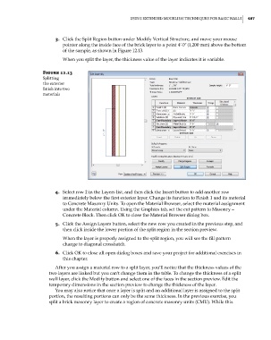
3. Click the Split Region button under Modify Vertical Structure, and move your mouse
pointer along the inside face of the brick layer to a point 4ʹ-0ʺ (1,200 mm) above the bottom
of the sample, as shown in Figure 12.13.
When you split the layer, the thickness value of the layer indicates it is variable.
Figure 12.13
splitting
the exterior
finish into two
materials
4. Select row 2 in the Layers list, and then click the Insert button to add another row
immediately below the first exterior layer. Change its function to Finish 1 and its material
to Concrete Masonry Units. To open the Material Browser, select the material assignment
under the Material column. Using the Graphics tab, set the cut pattern to Masonry –
Concrete Block. Then click OK to close the Material Browser dialog box.
5. Click the Assign Layers button, select the new row you created in the previous step, and
then click inside the lower portion of the split region in the section preview.
When the layer is properly assigned to the split region, you will see the fill pattern
change to diagonal crosshatch.
6. Click OK to close all open dialog boxes and save your project for additional exercises in
this chapter.
After you assign a material row to a split layer, you’ll notice that the thickness values of the
two layers are linked but you can’t change them in the table. To change the thickness of a split
wall layer, click the Modify button and select one of the faces in the section preview. Edit the
temporary dimensions in the section preview to change the thickness of the layer.
You may also notice that once a layer is split and an additional layer is assigned to the split
portion, the resulting portions can only be the same thickness. In the previous exercise, you
split a brick masonry layer to create a region of concrete masonry units (CMU). While this
c12.indd 487 5/3/2014 11:12:35 AM