
Page 522 - Divyank Tyagi
P. 522
488 | ChaPTER 12 Creating Walls and Curtain Walls
may achieve the desired graphic result in an elevation view, does it accurately represent the
construction of the wall if the CMU is intended to be thicker than the brick masonry? To create
a similar result with a vertical layer of varying thickness, you will need to create a stacked wall.
We will discuss this later in the section, “Creating Stacked Walls.”
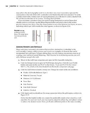
If you encounter a situation where you need to merge horizontal or vertical layers that
already exist in a wall type, use the Merge Regions button and select a line in the section
preview between two layers. Once the mouse pointer is over a line between two layers, an arrow
indicating which layer will override the other appears, as shown in Figure 12.14.
Figure 12.14
(a) Merge vertical
layers; (b) merge layers
that were previously
split.
(a) (b)
adding Sweeps and Reveals
Many walls have horizontal articulations that are either attached to or embedded in the
wall assembly. Cornices, soldier courses, and reveals are examples of elements that can be
incorporated into wall types. To begin adding these, we will continue our previous exercise of
creating a new wall type named Mastering - Wall Exercise. In the following exercise, you will
add a bullnose sweep to the wall:
1. Return to the wall’s type properties and open the Edit Assembly dialog box.
2. Click the Sweeps button to open the Wall Sweeps dialog box. Click the Load Profile
button and open the file c12-Profile-Bullnose.rfa or c12-Profile-Bullnose-
Metric.rfa, which can be downloaded from this book’s companion web page.
3. Click the Add button to insert a sweep row. Change the values in the row as follows:
◆ Profile: c12-Profile-Bullnose: Type 1
◆ Material: Concrete, Precast
◆ Distance: 4ʹ-0ʺ (1,200 mm)
◆ From: Base
◆ Side: Exterior
◆ Cuts Wall: Checked
◆ Cuttable: Checked
4. Click Apply and you should see the sweep appear just above the split region, as shown in
Figure 12.15.
Notice that the loaded profile was created for predictable results when placed in a wall
assembly. For your own wall, you may need to adjust the offset, flip, and setback values
to achieve the desired results. Next, you’ll add a different profile to the same assembly.
c12.indd 488 5/3/2014 11:12:36 AM