
Page 527 - Divyank Tyagi
P. 527
|
using extended Modeling teChniques for BasiC Walls 493
Extension Distance (depending on which edges you unlocked). You can enter this value directly
in the Properties palette or adjust it graphically in a section view by dragging the small blue
triangle control at the edge of the unlocked layer. Let’s go through an exercise to explore this
functionality:
1. From the Architecture tab of the ribbon, click the Wall tool and from the Type Selector
choose either the Generic - 5ʺ or Generic - 200 mm type. Click Edit Type to open the Type
Properties dialog box.
2. Click the Duplicate button, and name the new type Exterior Siding.
3. Click Edit in the Structure field to open the Edit Assembly dialog box.
4. Add a new layer to the exterior of the wall, set its function to Finish (4), use the material
Siding, Clapboard, and assign a thickness of 3/4ʺ (18 mm).
5. Open the Preview pane and switch to section view. Zoom into the bottom of the wall.
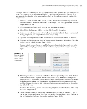
6. Select the Modify button and click the bottom edge of the exterior siding layer. Click the
padlock icon to unlock the layer (Figure 12.20).
You can unlock as many layers as you like; however, the unlocked layers all need to be
adjacent. For example, you cannot unlock wallboard layers on both sides of a framing
layer.
Figure 12.20
using the Modify
button, click the
padlock icon to
unlock layers.
7. The siding layer is now unlocked. Click OK to close all open dialog boxes. With the Wall
tool still active, create a segment of wall in the project using the Exterior Siding type.
Press Esc or click the Modify button, and then select the segment of wall you just created.
In the Properties palette, you’ll see that the Base Extension Distance parameter is now
enabled. Change the value to –10ʺ (–250 mm) for this parameter and observe the wall in
the default 3D view.
You’ll see that the siding layer is now extending 10ʺ (250 mm) below the base of the wall,
as shown in Figure 12.21.
8. Create a section view that intersects this wall segment, and then set the Detail Level in
the section view to Medium or Fine. Select the wall, and you will see grips at the base of
the wall indicating the layers that can be modified (Figure 12.22).
c12.indd 493 5/3/2014 11:12:43 AM