
Page 741 - Divyank Tyagi
P. 741
|
aDDing Detail CoMPonents to FaMilies 707
Adding Detail Components to Families
You have read in this chapter about the number of ways you can embellish a 3D model with 2D
detailing. We have discussed how to add detail elements as needed in the project environment,
but you can also include 2D elements inside families. The possibilities for this method are
almost limitless. You can add any kind of symbolic lines to 3D families, but in this section we
will focus on nesting a detail component in a profile family, which will then become the basis
for the curtain wall mullions in the sample project.
A more detailed review of curtain wall modeling is provided in Chapter 12, “Creating Walls
and Curtain Walls”. For now, we will simply edit the mullions already provided in the sample
building project to add some 2D detailing. Let’s get started by following these steps:
1. Continue working with the c16-Sample-Building.rvt or c16-Sample-Metric.rvt file
you downloaded from this book’s website. In the Project Browser, locate and activate
the section view named Section At Curtain Wall. It is located under the Sections (Wall
Section) branch of the Project Browser.
2. In the Project Browser, expand the Families branch, locate and expand the Profiles
branch, and then right-click Pr-Mullion-Horizontal or M_Pr-Mullion-Horizontal. Choose
Edit from the context menu and the mullion profile family will open.
The basic reference planes and profile lines have already been created.
You should already have downloaded the RFA files included with this chapter’s exercise
files. Among them are a series of detail components that represent the internal extrusion
details of the mullions in the sample project’s curtain wall system.
3. From the Create tab in the ribbon, click the Detail Component command. Browse to the
location where you downloaded this chapter’s exercise files and load the file named
Kawneer-1600-Sys1-Horizontal.rfa or M_Kawneer-1600-Sys1-Horizontal.rfa.
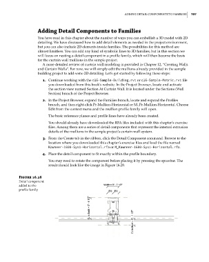
4. Place the detail component to fit exactly within the profile boundary.
You may need to rotate the component before placing it by pressing the spacebar. The
result should look like the image in Figure 16.28.
Figure 16.28
Detail component
added to the
profile family
c16.indd 707 5/3/2014 11:34:31 AM