
Page 743 - Divyank Tyagi
P. 743
|
aDDing Detail CoMPonents to FaMilies 709
9. Repeat the steps in this exercise for the head and sill mullion families. Edit the profile
families listed here (starts with Pr-Mullion) with the associated detail components (RFA
files) or their metric equivalents:
Pr-Mullion-Head > Kawneer-1600-Sys1-Head.rfa
Pr-Mullion-Sill > Kawneer-1600-Sys1-Sill.rfa
The detail components we used for this sample exercise were excerpted from real
manufacturer’s content that is available for free from the Kawneer website (www.kawneer.com).
Complete curtain wall system components for Revit are also available from their website.
You might have noticed that the curtain wall modeled in this chapter’s sample building
is somewhat simplified. For example, the bite of the glass panels inside the mullions is not
modeled; however, this condition appears in the detail component once you get down to a fine
level of detail. This exercise illustrates a hybrid approach to the balance between modeling and
detailing. If you download one of the Revit models from the Kawneer website (one sample is
provided with this chapter’s downloaded content), you will see that the glass panels are more
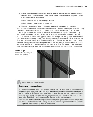
accurately modeled to include the mullion bite (Figure 16.31). In that scenario, you would not
need to include masking regions to simulate the glass panel in the mullion detail component.
Figure 16.31
More detailed modeling will
require less detailing.
Doors and Symbolic Lines
in the architecture industry, doors are typically modeled in a closed position but shown as open and
with a door swing direction in plan view. to get this dual representation, in the Family editor turn
off the visibility of the door panel (extruded solid form) in the plan view and draw the 90-degree
open door panel and its swing using symbolic lines. Control this visibility in the family environ-
ment using the Visibility settings explained in the next section of this chapter.
symbolic lines can be controlled using the same Visibility settings available for detail components
and the solid model elements in the family. You can use the same logic and draw the dashed lines
that represent the door-opening direction in elevations.
c16.indd 709 5/3/2014 11:34:33 AM