
Page 775 - Divyank Tyagi
P. 775
|
laYing out sheets 741
Let’s make some minor adjustments to the wall sample in the legend. Let’s change View to
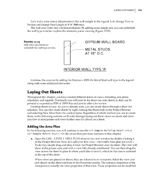
Section and change Host Length to 1ʹ-6ʺ (500 mm).
The wall now looks like a sectional element. By adding some simple text, you can embellish
the wall type to better explain the elements you’re viewing (Figure 17.25).
Figure 17.25
add other annotation to
embellish the wall type section.
Continue the exercise by adding the Exterior – EIFS On Metal Stud wall type to the legend
along with some additional text notes.
Laying Out Sheets
Throughout this chapter, you have created different kinds of views, including area plans,
schedules, and legends. Eventually you will need to lay those out onto sheets so they can be
printed or exported as PDF or DWF files and sent to others for review.
Creating sheets is easy. As you’ve already seen, you can create sheets through a sheet list
schedule. You can also create sheets by right-clicking the Sheet node in the Project Browser
and selecting New Sheet from the context menu. Regardless of which method you use to create
them, in the following sections we’ll walk through laying out these views on sheets and show
you how to manipulate each view further once it’s placed on a sheet.
adding the area Plan
In the following exercise, you will continue to use the c17-Sample-Building-Start.rvt or
c17-Sample-Metric-Start.rvt file saved from previous exercises in this chapter:
1. Open the G101 – LEVEL 1 AREA PLAN sheet in the view window by double-clicking it
in the Project Browser. Now, let’s add your first view—the Usable Area plan for Level 1.
To do this, simply drag and drop it from the Project Browser onto the sheet. The view will
show at the proper scale and with a view title already established. You can then drag the
view across the sheet to place it where you’d like to have it, which in this case is centered
at the top of the sheet.
When views are placed on sheets, they are referred to as viewports. Select the view you
just placed on the sheet and look at the Properties palette. The instance properties of the
viewport are actually the view properties of that view. These properties can be modified
c17.indd 741 5/3/2014 11:46:30 AM