
Page 848 - Divyank Tyagi
P. 848
814 | ChaPteR 19 Working in the ConstruCtion Phase
Using Parts
so far in this chapter, you’ve seen how you can use parts to subdivide building elements such as
walls and floors. While the workflow outlined can take away from quickly laying out walls and
floors, the Parts tool is very useful if leveraged correctly. as an example, one use for the Parts tool
would be to define precast panels. in many instances, the precast paneling follows architectural
grid lines. Controlling those with hosted voids or sweeps can be very cumbersome and lead to a lot
of manual coordination. hosted sweeps can also be problematic around windows or other openings
in the panels. This workflow would allow you to dynamically update the design and have it resonate
through the documents quickly and clean up more easily than sweeps.
knowing when to make use of a tool in revit is almost as important as knowing how to use the
tool. tools like Parts that allow a very granular manipulation of building geometry are typically
better left until later in the design process.
Dividing Parts with a Gap
In the previous exercise, you learned how to divide parts using datum objects and simple
sketches. You also have the ability to divide parts with a defined gap as well as with a custom
profile. Let’s explore these options with another exercise:
1. Continue to work with the sample file c19-Parts-Start.rvt or c19-Parts-Metric-
Start.rvt from the previous exercise. Activate the Parts Model 3D view and orbit the
model to view the exterior face of the wall.
2. Select the main part of the exterior wall face that has the material assignment Concrete,
Precast. Click the Divide Parts tool in the contextual ribbon.
3. In the Properties palette, set the Divider Gap parameter to 1ʺ (25 mm).
4. Click the Intersecting References tool in the ribbon, set the filter to All, and then select
Level 2, Reference Plane: yPlane1, and Grid: 1. Click OK to close the dialog box.
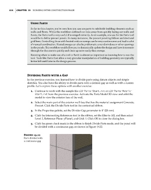
5. Click the green check mark in the ribbon to finish Divide Parts mode, and the panel will
be divided with a continuous gap, as shown in Figure 19.22.
Figure 19.22
Parts divided with
a continuous gap
c19.indd 814 05-05-2014 16:22:45