
Page 843 - Divyank Tyagi
P. 843
|
MoDeling For ConstruCtion 809
In Mastering Autodesk Revit Architecture 2011 (Wiley, 2010), we wrote about a technique to
manually model each individual layer of a wall assembly to better understand the construction
of the wall. This technique also supported more enhanced phasing and even construction
sequencing simulation using software such as Autodesk® Navisworks®. The drawback to this
approach was the complexity in managing far more building elements, and it was usually used
by only the builder.
Functionality introduced in Revit Architecture 2012 supports a more interactive and flexible
approach to construction modeling. The first addition was the ability to create parts, which
are individual subsets of more complex layered elements such as walls and floors. The other
addition allowed you to generate assemblies, which are segregated subsets of the project model
with their own associated views, annotations, and sheets. These tools are used to take large
elements and break them down into smaller components as they’d be used on the job site. As
an example, in an architectural model, a cast-in-place concrete floor would be a single element
for the entire floor plate. In practice, the contractor would never pour the floor that way. The
concrete would be poured in a series of pads, and the contractor would have to divide the
slab into those series of pours for their schedule. The potential to minimize data loss between
the design and construction stakeholders of a project can start to change how we approach
collaboration and delivery of our buildings.
Creating Parts
Parts are designed to aid the user in subdividing larger model elements into smaller
components for construction planning. Each part maintains a persistent relationship with the
elements from which it was derived, and it can be subdivided into smaller parts if necessary.
Parts can be generated from walls, floors, ceilings, and roofs, as long as they are of consistent
thickness. They also have their own properties, such as volume, area, and height; as such they
can be scheduled independently of their original elements.
While it is likely that designers will use Parts to customize architectural elements, we are
going to discuss only the workflow intended for the builder. To get started with the basic
workflow for creating and dividing parts, follow these steps:
1. Open the file c19-Parts-Start.rvt or c19-Parts-Metric-Start.rvt, which you can
download from this book’s companion website.
2. Activate the Default 3D view if it isn’t already open.
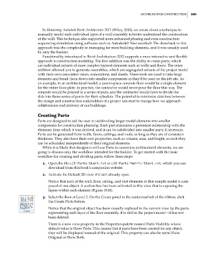
Notice that each of the wall, floor, ceiling, and roof elements in this sample model is com-
posed of one object. A section box has been activated in this view that is exposing the
layers within each element (Figure 19.16).
3. Select the floor at Level 2. On the Create panel in the contextual tab of the ribbon, click
the Create Parts button.
Notice that the original object has been visually replaced in the current view by the parts
representing each layer of the floor assembly. It is still in the project model—it has not
been deleted.
There is a new view property in the Properties palette named Parts Visibility whose
default value is Show Parts. This means that if parts have been created for any object,
they will be displayed instead of the original. This property can also be set to Show
Original or Show Both.
c19.indd 809 05-05-2014 16:22:43