
Page 845 - Divyank Tyagi
P. 845
|
MoDeling For ConstruCtion 811
1. Go back to the Parts Model view and select the top part of the roof at the Roof level.
This will be the layer representing insulation.
2. From the Part panel in the contextual ribbon, click Divide Parts.
You will enter Sketch mode, where you can either select intersecting datum or draw your
own dividing lines.
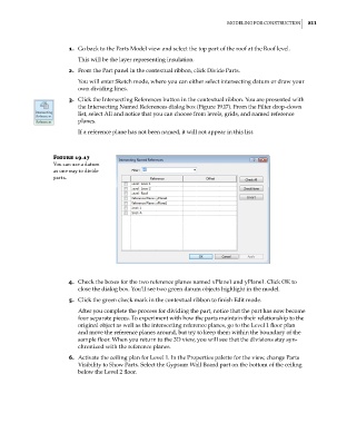
3. Click the Intersecting References button in the contextual ribbon. You are presented with
the Intersecting Named References dialog box (Figure 19.17). From the Filter drop-down
list, select All and notice that you can choose from levels, grids, and named reference
planes.
If a reference plane has not been named, it will not appear in this list.
Figure 19.17
You can use a datum
as one way to divide
parts.
4. Check the boxes for the two reference planes named xPlane1 and yPlane1. Click OK to
close the dialog box. You’ll see two green datum objects highlight in the model.
5. Click the green check mark in the contextual ribbon to finish Edit mode.
After you complete the process for dividing the part, notice that the part has now become
four separate pieces. To experiment with how the parts maintain their relationship to the
original object as well as the intersecting reference planes, go to the Level 1 floor plan
and move the reference planes around, but try to keep them within the boundary of the
sample floor. When you return to the 3D view, you will see that the divisions stay syn-
chronized with the reference planes.
6. Activate the ceiling plan for Level 1. In the Properties palette for the view, change Parts
Visibility to Show Parts. Select the Gypsum Wall Board part on the bottom of the ceiling
below the Level 2 floor.
c19.indd 811 05-05-2014 16:22:44