
Page 133 - C:\Users\Adik\Documents\Flip PDF Professional\Marketer PPT LR\
P. 133
Example #1:
Assume a part is 10"x 12"x 2" deep. Therefore the Draw Ratio will be:
Surface Area = 2(10" x 2") + 2(12"x2") + 10" x 12” = 40" + 48" + 120” = 208”
Footprint = 10" x 12” = 120"
Draw Ratio = 208"/120” = 1.7
If the desired ending wall thickness of the part is 0.100" use the draw ratio as follows
to estimate the starting gauge of the sheet:
Draw Ratio x Desired Finished Gauge = Minimum Starting Gauge
1.7 x 0.100" = 0.170" Assuming perfect material distribution.
Example #2:
Assume a part size of 10" x 11" x 5" deep.
Surface Area = 2(10" x 5") + 2(11" x 5") + (10" x 11") = 300”
Footprint = 10" x 11" = 110”
Draw Ratio = 2.73
If the desired ending wall thickness is 0.100" use the draw ratio value as follows:
2.7 x 0.100" = 0.273" starting gauge. Assuming perfect material distribution.
6
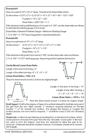
Cavity Mould Linear Draw Ratio
Length of line prior to forming = 6"
6”
Length of line after forming = 6" + 3" + 6" = 15"
Linear Draw Ratio = 15/6 = 2.5
3”
Thus the sheet would stretch 2.5 times its original length.
3”
Length of line prior to forming = 10"
6” Length of line after forming =
2" + 6" + 3" + 6" + 2" = 19"
2”
Linear Draw Ratio = 19/10 = 1.9
10”
Clamping Frame Here the sheet would stretch 1.9 times its original length.
Draft (taper): Draft is the degree of taper of a vertical sidewall to facilitate removal of
the part from the tool. Male moulds: 3° minimum required whereas for Female
moulds: 1°--2º for smooth tool surface. The deeper the feature or rougher the
surface texture, the more draft is required, 1° of draft for every 0.025 mm of texture
depth.
Undercuts: Undercuts are features protruding from or into the tool surface, which
would prevent removal of the part from the tool. Movable “cores-pulls” in the tool
are used to form the feature, and then are retracted to allow the part to be
removed. Undercuts should be avoided however, if necessary should not to exceed
5/8” in depth.
DAVE TECHNICAL SERVICES 133