
Page 211 - Maxwell House
P. 211
SOLUTION OF BASIC EQUATIONS OF ELECTRODYNAMICS 191
It is worthwhile to point out the described merging of two
radiators develops unidirectional or simply directional
antenna in both E- and H-plane with effectively suppressed
back radiation. Replacing the magnetic dipole with the
loop that has the same field structure, we can get the
simplest practical directional antenna like shown
schematically in Figure 4.3.10 and comprises collateral
loop and vertical dipole shown in blue. Application of such
antennas for TV indoor reception lets reduce (not very
much) the effect of possible multiple reflections of TV
Figure 4.3.10 Directional signal from the walls of a house and people moving in the
antenna room.
4.4 SKIN EFFECT
4.4.1 Skin Effect in Conductive Materials. Impact of Surface Roughness
Almost everything that has been done before was about the radiators and EM wave’s
propagation in free-of-loss unbounded mediums. Now, let us look back at equations (4.13) –
(4.15) and the solution (4.60) for the vector potential in a lossy medium keeping it unbounded.
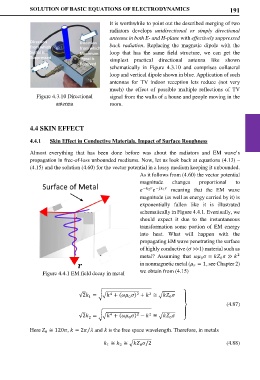
As it follows from (4.60) the vector potential
magnitude changes proportional to
− 2 − 1 meaning that the EM wave
magnitude (as well as energy carried by it) is
exponentially fallen like it is illustrated
schematically in Figure 4.4.1. Eventually, we
should expect it due to the instantaneous
transformation some portion of EM energy
into heat. What will happen with the
propagating EM wave penetrating the surface
of highly conductive ( >>1) material such as
metal? Assuming that = ≫
2
0 0
in nonmagnetic metal ( = 1, see Chapter 2)
Figure 4.4.1 EM field decay in metal we obtain from (4.15)
2
4
2
√2 = �� + ( ) + ≅ � ⎫
1
0
0
⎪
(4.87)
⎬
4
2
2
√2 = �� + ( ) − ≅ � ⎪
0
0
2
⎭
Here ≅ 120, = 2 and is the free space wavelength. Therefore, in metals
⁄
0
≅ ≅ � /2 (4.88)
1
2
0