
Page 284 - Maxwell House
P. 284
264 ANTENNA BASICS
are interrelated through the two electric lengths: = ( + 1) and = ( + 1) .
Since they are independent, the designer can realize (depending on system specification) a wide
diversity of patterns with different shapes in the elevation and azimuth plane. For example, the
pattern can be broad in elevation plane and much narrower in azimuth (typical for air traffic
control radars) or vice versa (typical for broadcast and some communication systems). Figure
5.6.4a depicts this kind of patterns. Note that the level of the highest sidelobes is around -13dB
in both planes which is just slightly lower than in linear array with the same uniform excitation.
The sidelobe level (SLL) and the pattern with specially shaped envelope can be controlled by
an appropriate inter-element, magnitude and sometimes phase tapering or weighting in the same
way as in linear arrays. In particular, the excitation reduction from the maxima in the array
center to its edges actually reduces SLL but widens the main beam as Figure 5.6.4b depicts.
Chebyshev’s or any other synthesis technique can be applied independently for each pattern
cut. Figure 5.6.4b demonstrates the one plane sinus-tapered when | | = 1, | | =
sin � � , = 0,1, … , . As expected, SLL peak drops to -23.2dB in the azimuth cut = 0 and
does not change, i.e. around -13dB, in the cross section = 90°.
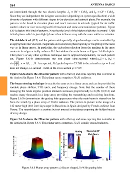
Figure 5.6.5a shows the 2D sector pattern with a flat top and sinus-tapering that is similar to
the depicted in Figure 5.4.4. This planar array comprises 31x31 radiators.
The beam steering technique is exactly the same as in a linear array and can be provided by
variable phase shifters, TTD units, and frequency change. Note that the number of these
managing the beam angular position elements increases proportionally to 2∙(M+1)∙(N+1) and
reaches many thousands in a large array providing the transmitting and receiving functions.
Figure 5.6.5b demonstrates the grating lobe appearance when the main beam is steered too far
from the zenith by a plane array of 16x16 radiators. The picture-in-picture is the image of a
142-meter-high (466 feet) skyscraper in Barcelona in Spain designed by French architect Jean
Nouve. The resemblance is a curious but not unusual coincidence exposing the hidden beauty
of array design.
Figure 5.6.5a shows the 2D sector pattern with a flat top and sinus-tapering that is similar to
the depicted in Figure 5.4.4. This planar array comprises 31x31 equally spaced radiators.
Grating Steered at 60
Lobe Main Beam
a) b)
Figure 5.6.5 Planar array pattern: a) Sector-shaped, b) With grating lobe