
Page 285 - Maxwell House
P. 285
Chapter 5 265
Pay attention to ripples on flat-top of almost perfectly shaped sector pattern with a sharp roll-
off and low level (below -25 dB) of SLL that is provided by the excitation tapering. Antenna
arrays with such type of pattern are commonly used in the base stations of cellular
communication systems to maximize the gain and reduce interference. For example, large
number of radiators in massive MIMO of 5G-systems (see Section 5.3.6 of this chapter) makes
possible to form the patterns of such type in spatially separated sectors and reuse the same set
of frequency channels in each sector. Keep in mind that the steering techniques described in
Section 5.5 of this chapter allow controlling the pattern characteristics very fast in space as well
in time.
The beam steering technique is exactly the same as in a linear array and can be provided by
variable phase shifters, TTD units, and frequency change. Note that the number of these
managing the beam angular position elements increases proportionally to 2∙(M+1)∙(N+1) and
reaches many thousands in a large array providing the transmitting and receiving functions.
Figure 5.6.5b demonstrates the grating lobe appearance when the main beam is steered too far
from the zenith by a plane array of 16x16 radiators. The picture-in-picture is the image of a
142-meter-high (466 feet) skyscraper in
Barcelona in Spain designed by French
architect Jean Nouve. The resemblance
is a curious but not unusual coincidence
exposing the hidden beauty of array
design. A planar array, like a linear
array, is capable of generating
(M+1)∙(N+1) independent beams when
connected to analog or digital
beamformer.
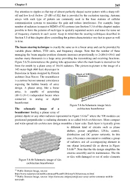
Figure 5.6.6a Schematic image brick-
The schematic image of a architecture beamformer
beamformer feeding a planar array of
27
printed dipole or any other radiators ispresented in Figure 5.6.6a where the T/R modules are
positioned perpendicular to radiating elements in so-called brick-architecture. More compact
and wide-spread tile-architecture design resembles a layer cake. Each layer is typically given
to different kind of circuits such as phase
shifters, power amplifiers, LNAs, control,
distribution and DC power networks. In this
case, it becomes convenient to combine a group
of radiators and all accompanying element in
one planar horizontal tile as shown in Figure
5.6.6b . Note that the tile design simplifies the
28
antenna assembly and its maintenance. The tile
or tiles with damaged or out of order elements
Figure 5.6.6b Schematic image of tile-
architecture beamformer
27 Public Domain Image, source:
http://www.radartutorial.eu/06.antennas/Phased%20Array%20Antenna.en.html
28 Public Domain Image, source: https://artes.esa.int/projects/planar-array-active-antennas-mobile-
terminals