
Page 286 - Maxwell House
P. 286
266 ANTENNA BASICS
can be replaced without breaching the remaining antenna structure.
5.6.2 Conformal Arrays
In some cases, an array of radiators that includes the occurrence of single radiator must be
placed on the smooth curved surface like some parts of an airplane, missile or satellite, on train
roof or communication tower body, etc. This class of arrays is customarily called conformal
arrays and sketchily shown in Figure 5.6.7a where each radiator is depicted as a green patch.
To be precise, the planar array is the particular case of the conformal array, but the prevailing
practice is to consider them separately [9, 10]. The IEEE Standard Definition of Terms for
Antennas (IEEE Std 145-1993, section 2.74) defines a conformal antenna as “… An antenna
that conforms to a surface whose shape is determined by considerations other than
electromagnetic; for example, aerodynamic or hydrodynamic.” For example, the antenna array
on aircraft must be an integral part of its body to avoid extra drag, communication arrays on the
tower must satisfy aesthetic requirements to be less visible to human eye, etc. The conformal
antenna is a critical fragment of stealth technology. It can be explained by the fact that a planar
array, in general, focuses and reflects back the incident plane wave almost like a metal plate.
Meanwhile, the same antenna on the curved surface defocuses and scatters the energy within
wider angular sector thereby reducing more or less the RF energy reflected back to the “phishing
peeking-eye.”
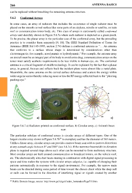
Figure 5.6.7 a) Radiators printed on conformal surface, b) Circular array, c) Azimuth beam
scan
The particular subclass of conformal arrays is circular arrays of different types. One of the
29
largest circular array shown in Figure 5.6.7b is exemplary and has the diameter of 365 meters.
Unlike a linear array, circular arrays can provide a narrow beam scan with no pattern distortions
at any azimuth angle between 0° and 360° (see 5.6.7c). If the narrower beamwidth in elevation
plane is required several rings above each other can be mounted to form multistory structure.
Most circular arrays are built around communication or broadcast towers, on the vehicle roof,
etc. The electronically ultra-fast beam steering in combination with digital signal processing in
space and time makes the systems with circular arrays adaptive, i.e. capable of changing their
patterns automatically in response to the signal environment. For example, the narrow main
beam can be directed during some period of time toward the chosen client while the deep null
or nulls can be formed in the direction of interfering signal or signals created by another
29 Public Domain Image, source: http://www.pa3clq.nl/index_bestanden/Page531.htm