
Page 281 - Maxwell House
P. 281
Chapter 5 261
sin ((+1)(cos−cos 1 )/2)
() = (+1)(cos−cos 1 )/2 +
Σ
sin ((cos−cos 1 )/2) (5.103)
sin ((+1)(cos−cos 2 )/2) (+1)(cos−cos 2 )/2
sin ((cos−cos 2 )/2)
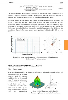
This pattern consists of two beams pointed in different directions and as shown in Figure
1 2
5.5.9b. The described procedure can clearly be extended to more than two beams. Note that in
principle, an N-element array cannot generate more than N independent beams.
It is useful to point out that multiple beams allow us to realize parallel signal processing and
thereby a higher data rate than a single beam screening the space in sequence. In some
applications, multiple beams are generated by the transmitting or receiving antenna (or both)
and connected to separate generators or receivers. In general, such an approach requires the
development of so-called Butler or Blass analog or digital beamformers. We will discuss this
topic later in Chapter 8. The reader can also turn to specialized publications [18 - 20] for more
details.
Figure 5.5.9 Linear array forming two independent beams: a) Relative power
distribution, b) Twin beam pattern
5.6 PLANAR AND CONFORMAL ARRAYS
5.6.1 Planar Arrays
As we have demonstrated before, linear arrays of isotropic radiators develop a directional and
steerable pattern in the elevation
plane only while they keep the
omnidirectivity in the azimuth
plane. To make the pattern more
versatile and more symmetrical,
several linear arrays can be
placed next to each other in the
same plane to form a planar
array as demonstrated in Figure
5.6.1a and schematically Figure 5.6.1 a) Planar array in XY-plane, b)
Geometry of planar array in spherical coordinates