
Page 348 - Maxwell House
P. 348
328 Chapter 6
As we have mentioned before, a high concentration of electrical and magnetic fields around the
sharp edges of traces (see edge effect described in Chapter 3) causes the extremely high density
of electrical current there. In other words, the conductor losses dominate, and the slot line is
lossier than microstrip line. The same effect of E-field concentration seriously restricts the
power handling.
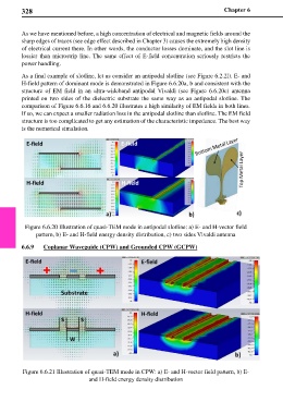
As a final example of slotline, let us consider an antipodal slotline (see Figure 6.2.2l). E- and
H-field pattern of dominant mode is demonstrated in Figure 6.6.20a, b and consistent with the
structure of EM field in an ultra-wideband antipodal Vivaldi (see Figure 6.6.20c) antenna
printed on two sides of the dielectric substrate the same way as an antipodal slotline. The
comparison of Figure 6.6.16 and 6.6.20 illustrates a high similarity of EM fields in both lines.
If so, we can expect a smaller radiation loss in the antipodal slotline than slotline. The EM field
structure is too complicated to get any estimation of the characteristic impedance. The best way
is the numerical simulation.
Figure 6.6.20 Illustration of quasi-TEM mode in antipodal slotline: a) E- and H-vector field
pattern, b) E- and H-field energy density distribution, c) two sides Vivaldi antenna
6.6.9 Coplanar Waveguide (CPW) and Grounded CPW (GCPW)
Figure 6.6.21 Illustration of quasi-TEM mode in CPW: a) E- and H-vector field pattern, b) E-
and H-field energy density distribution