
Page 347 - Maxwell House
P. 347
FEED LINE BASICS 327
As expected for quasi-TEM mode:
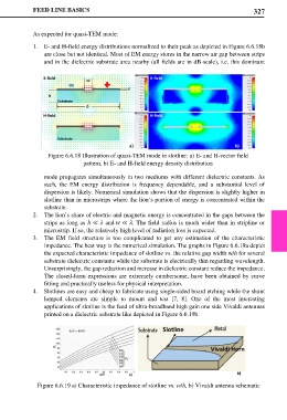
1. E- and H-field energy distributions normalized to their peak as depicted in Figure 6.6.18b
are close but not identical. Most of EM energy stores in the narrow air gap between strips
and in the dielectric substrate area nearby (all fields are in dB-scale), i.e. this dominant
Figure 6.6.18 Illustration of quasi-TEM mode in slotline: a) E- and H-vector field
pattern, b) E- and H-field energy density distribution
mode propagates simultaneously in two mediums with different dielectric constants. As
such, the EM energy distribution is frequency dependable, and a substantial level of
dispersion is likely. Numerical simulation shows that the dispersion is slightly higher in
slotline than in microstrips where the lion’s portion of energy is concentrated within the
substrate.
2. The lion’s share of electric and magnetic energy is concentrated in the gaps between the
strips as long as ℎ ≪ and ≪ . The field radius is much wider than in stripline or
microstrip. If so, the relatively high level of radiation loss is expected.
3. The EM field structure is too complicated to get any estimation of the characteristic
impedance. The best way is the numerical simulation. The graphs in Figure 6.6.19a depict
the expected characteristic impedance of slotline vs. the relative gap width w/h for several
substrate dielectric constants while the substrate is electrically thin regarding wavelength.
Unsurprisingly, the gap reduction and increase in dielectric constant reduce the impedance.
The closed-form expressions are extremely cumbersome, have been obtained by curve
fitting and practically useless for physical interpretation.
4. Slotlines are easy and cheap to fabricate using single-sided board etching while the shunt
lumped elements are simple to mount and test [7, 8]. One of the most interesting
applications of slotline is the feed of ultra-broadband high gain one side Vivaldi antennas
printed on a dielectric substrate like depicted in Figure 6.6.19b.
Figure 6.6.19 a) Characteristic impedance of slotline vs. w/h, b) Vivaldi antenna schematic