
Page 342 - Maxwell House
P. 342
322 Chapter 6
Evidently, this ratio frequency independent as long as the metal elements of line is perfectly
conductive and dielectric parameters are independent of frequency.
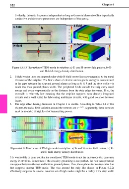
Figure 6.6.13 Illustration of TEM-mode in stripline: a) E- and H-vector field pattern, b) E-
and H-field energy density distribution.
2. E-field vector lines are perpendicular while H-field vector lines are tangential to the metal
elements of the stripline. The lion’s share of electric and magnetic energy is concentrated
in the gaps between the strip and ground planes as long as ℎ ≪ and the strip width w is
much less than ground planes width. The peripheral fields outside the strip carry small
energy and decay exponentially as the distance from the strip edges increases. If so, the
crosstalk is relatively low meaning that the stripline supports more densely integrated
circuits and is well suited for fabricating multilayer circuits, with good isolation between
layers.
3. The edge effect having discussed in Chapter 3 is visible. According to Table 3.1 of this
⁄
chapter, the radial field variation around the vertexes are −1 3 . Apparently, these vertexes
must be rounded at high level of transmitting power.
Figure 6.6.14 Illustration of TE-high mode in stripline: a) E- and H-vector field pattern, b) E-
and H-field energy density distribution
It is worthwhile to point out that the considered TEM-mode is not the only mode that can carry
energy in stripline. Sometimes if the circuitry grounding is not perfect, the non-zero potential
can appear between the top and bottom ground planes. If so, these planes form a two-wire line
that supports another TEM-mode. The vias around the strip like shown in Figure 6.2.2r
effectively suppress this mode. Another set of high modes might be a reality if the strip width