
Page 338 - Maxwell House
P. 338
318 Chapter 6
the first column of Figure 6.6.9b.
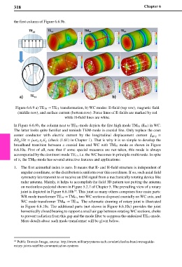
Figure 6.6.9 a) TE10 → TE11 transformation, b) WC modes: E-field (top row), magnetic field
(middle row), and surface current (bottom row). Force lines of E-fields are marked by red
while H-field lines are white.
In Figure 6.6.9b, the column next to TE11-mode depicts the first high mode TM01 (E01) in WC.
The latter looks quite familiar and reminds TEM-mode in coaxial line. Only replace the coax
center conductor with electric current by the longitudinal displacement current =
= (check (1.61) in Chapter 1). That is why it is so simple to develop the
⁄
0
broadband transition between a coaxial line and WC with TM01 mode as shown in Figure
6.6.10a. First of all, note that if some special measures are not taken, this mode is always
accompanied by the dominant mode TE11, i.e. the WC becomes in principle multimode. In spite
of it, the TM01-mode has several attractive features and applications:
1. The first azimuthal index is zero. It means that E- and H-field structure is independent of
angular coordinate, or the distribution is uniform over this coordinate. If so, such axial field
symmetry lets transmit to or receive an EM signal from a mechanically rotating device like
radar antenna. Mainly, it helps to accomplish the field 3D pattern test putting the antenna
on motionless pedestal shown in Figure 5.2.7 of Chapter 5. The prevailing view of a rotary
joint is depicted in Figure 6.6.10b . This joint as many others comprises four main parts:
16
WR mode transformer TE10 → TM01, two WC sections disposed coaxially on WC axis, and
WC mode transformer TM01 → TE10. The schematic drawing of rotary joint is illustrated
in Figure 6.6.10c. The additional parts (not shown in Figure 6.6.10c) provides the joint
hermetically closed bearing to support a small air gap between rotating WC sections, choke
to prevent radiation from this gap and the mode filter to suppress the undesired TE11-mode.
More details about such mode transformer will be given below.
16 Public Domain Image, source: http://www.militarysystems-tech.com/articles/ku-band-waveguide-
rotary-joints-satellite-communication-systems