
Page 335 - Maxwell House
P. 335
FEED LINE BASICS 315
The equities in (6.35) demonstrate the exponential decay of EM fields over the z-axis typical
for reactive fields and the phase shift of 90° (factor = /2 ) between electric and all magnetic
components. It is important to point out that such decay is not caused by any kind of energy
dissipation and indicates that the waveguide sections below cutoff behaves as an energy storage
element likewise an inductor or capacitor and can be used in this role. The reactive modes below
the cutoff frequencies were called evanescent modes.
If so, does such exotic regime have any practical importance if the energy transfer in WR stops
altogether? Let us think through several applications:
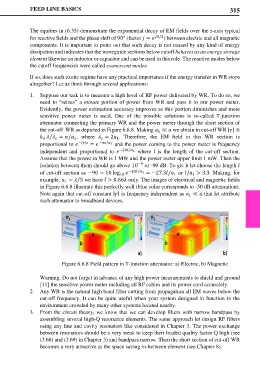
1. Suppose our task is to measure a high level of RF power delivered by WR. To do so, we
need to “seizes” a minute portion of power from WR and pass it to our power meter.
Evidently, the power estimation accuracy improves as this portion diminishes and more
sensitive power meter is used. One of the possible solutions is so-called T-junction
attenuator connecting the primary WR and the power meter through the short section of
the cut-off WR as depicted in Figure 6.6.8. Making ≪ we obtain in cut-off WR || ≅
1
= / , where = 2 . Therefore, the EM field in this WR section is
⁄
0 1 1
proportional to −|| = −/ 1 and the power coming to the power meter is frequency
independent and proportional to −2/ 1 where l is the length of the cut-off section.
Assume that the power in WR is 1 MW and the power meter upper limit 1 mW. Then the
−9
isolation between them should go above 10 or -90 dB. To get it let choose the length
of cut-off section as −90 = 10 log 10 −2/ 1 = −27.3/ or / > 3.3. Making, for
1
1
example, = /5 we have > 0.66 only. The images of electrical and magnetic fields
1
in Figure 6.6.8 illustrate this perfectly well (blue color corresponds to -50 dB attenuation).
Note again that cut-off constant || is frequency independent as ≪ that let attribute
1
such attenuator to broadband devices.
Figure 6.6.8 Field pattern in T-junction attenuator: a) Electric, b) Magnetic
Warning. Do not forget in advance of any high power measurements to shield and ground
[11] the sensitive power meter including all RF cables and its power cord accurately.
2. Any WR is the natural high band filter cutting from propagation all EM waves below the
cut-off frequency. It can be quite useful when your system designed to function in the
environment crowded by many other systems located nearby.
3. From the circuit theory, we know that we can develop filters with narrow bandpass by
assembling several high-Q resonance elements. The same approach let design RF filters
using any line and cavity resonators like considered in Chapter 3. The power exchange
between resonators should be a very weak to keep their loaded quality factor Q high (see
(3.68) and (3.69) in Chapter 3) and bandpass narrow. Then the short section of cut-off WR
becomes a very attractive as the space saving in-between element (see Chapter 8).