
Page 334 - Maxwell House
P. 334
314 Chapter 6
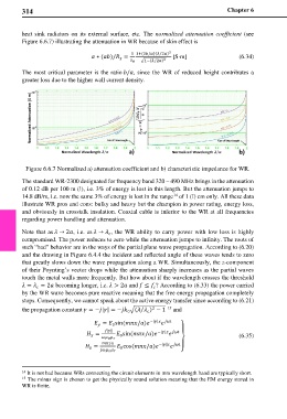
heat sink radiators on its external surface, etc. The normalized attenuation coefficient (see
Figure 6.6.7) illustrating the attenuation in WR because of skin effect is
1 1+(2/)( 2) 2
⁄
∗ ()/ = [S⋅m] (6.34)
⁄
0 �1−( 2) 2
The most critical parameter is the ratio /, since the WR of reduced height contributes a
greater loss due to the higher wall current density.
Figure 6.6.7 Normalized a) attenuation coefficient and b) characteristic impedance for WR.
The standard WR-2300 designated for frequency band 320 – 490 MHz brings in the attenuation
of 0.12 dB per 100 m (!), i.e. 3% of energy is lost in this length. But the attenuation jumps to
14.8 dB/m, i.e. now the same 3% of energy is lost in the range of 1 (!) cm only. All these data
14
illustrate WR pros and cons: bulky and heavy but the champion in power rating, energy loss,
and obviously in crosstalk insulation. Coaxial cable is inferior to the WR at all frequencies
regarding power handling and attenuation.
Note that as → 2, i.e. as → , the WR ability to carry power with low loss is highly
compromised. The power reduces to zero while the attenuation jumps to infinity. The roots of
such “bad” behavior are in the ways of the partial plane wave propagation. According to (6.20)
and the drawing in Figure 6.4.4 the incident and reflected angle of these waves tends to zero
that greatly slows down the wave propagation along a WR. Simultaneously, the z-component
of their Poynting’s vector drops while the attenuation sharply increases as the partial waves
touch the metal walls more frequently. But how about if the wavelength crosses the threshold
= = 2 becoming longer, i.e. > 2 and ≤ ? According to (6.33) the power carried
by the WR wave becomes pure reactive meaning that the free energy propagation completely
stops. Consequently, we cannot speak about the active energy transfer since according to (6.21)
15
the propagation constant = −|| = − �( ) − 1 and
2
⁄
0
= sin (/) −|| ⎫
0
|| −|| ⎪
= sin (/) (6.35)
0
0
⎬
/ −||
= cos (/) ⎪
0
0 ⎭
14 It is not bad because WRs connecting the circuit elements in mm wavelength band are typically short.
15 The minus sign is chosen to get the physically sound solution meaning that the EM energy stored in
WR is finite.