
Page 337 - Maxwell House
P. 337
FEED LINE BASICS 317
critical wavelength of the dominant mode 1 = 3.4129 where r is WC radius but be less than
the critical wavelength of the first high mode 2 = 2.6126 (see later). Typically, the
⁄
operation wavelength is chosen around the middle = ( 1 + ) 2 ≅ 3 meaning that ≅
2
/3. The key features like the attenuation and power handling of a single mode WR and WC
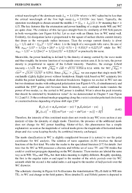
are quite close. The evidence of this fact goes straight from the similarity of EM field pattern
in both waveguides (see Figure 6.6.9a). Let us start with an Ohmic loss in WC metal wall.
Evidently, the dissipation factor proportional to the square of surface electric current density
that drops as the waveguide radius increases. Then the average current density is about
~ 1 and ~ ( ) ~ 1 where is the length of a waveguide tube curve. In case of
2
2
⁄
⁄
2
2
2
2
WR ~ 1 = 1 (2 + 2) = 1 (2 ∙ 0.7 + 2 ∙ 0.35) = 0.227/ while for WC
⁄
⁄
⁄
2
2
2
2
⁄
⁄
~ 1 = 1 (2) = 1 (2/3) = 0.228/ or practically the same.
⁄
Meanwhile, the power handling is defined by the density of energy carried by the wave mode
and thus roughly the inverse function of waveguide cross section area . In its turn, the power
density is proportional to square of the E-field intensity. Therefore, the average E-field
intensity ~ 1 √. For WR � = √ = √0.7 ∙ 0.35 ≅ 0.5 while for WC � =
⁄
2
2
√ = �3.14 ∙ (/3) ≅ 0.59. Since � > � we can expect that single mode WC
can handle slightly higher power without breakdown. Simple trick based on WC symmetry lets
double the power handling without electrical breakdown. Suppose we excited in WC not one
but two dominant modes with orthogonal polarization (see Figure 6.4.5c, d) simultaneously and
establish the ±90° phase shift between them. Evidently, such combined mode transfers the
power of two modes, i.e. the carried in WC power is doubled. What is about the peak intensity
that should be restricted by breakdown value? As we demonstrated in Chapter 5 (see Figure
5.1.2 and 5.1.3) the combined mode propagating along the -axis is circular polarized clockwise
or counterclockwise depending of phase shift sign ±90°
(, ) = cos( − ) ∓ sin( − )
0 0
±
0 0
2 � (6.41)
2
2
2
� (, )� = �cos ( − ) + sin ( − )� = 0 2
0
±
Therefore, the intensity of this combined mode does not overdo in any WC cross section at any
moment of time the intensity of single mode. Therefore, the presence of the additional mode
does not change the WC power handling. Matter-of-fact, this phenomenon has a simple
explanation: as soon as the magnitude of vertical mode grows the magnitude of horizontal mode
drops and vice versa keeping thereby the combined intensity unchanged.
The mode classification in WC is slightly complicated because it is natural to use the polar
coordinates for WC analysis. The solution of wave equations (6.28) involves the Bessel
functions of the first kind. We refer the reader to the specialized literature [17] for details. Just
note that the WC as WR possesses a discrete and infinite set of wave TE- and TM-modes that
could or could not propagate depending on the WC diameter. These modes are labeled the same
way as in WR: TEmn and TMmn but their index meaning is slightly different. Roughly speaking,
the first is the angular index m and equal to the number of the whole periods over the WC
azimuth while the second is the radial index n and equal to the number of half-periods over the
WC diameter.
The schematic drawing in Figure 6.6.9a illustrates the transformation TE10 E-field in WR into
TE11 in WC and change in the field pattern. More detailed E- and H-field pattern is depicted in