
Page 340 - Maxwell House
P. 340
320 Chapter 6
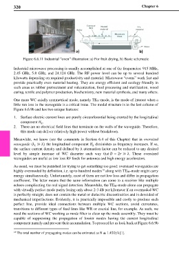
Figure 6.6.11 Industrial “oven” illustration: a) For fruit drying, b) Basic schematic
Industrial microwave processing is usually accomplished at one of the frequencies: 915 MHz,
2.45 GHz, 5.8 GHz, and 24.124 GHz. The RF power level can be up to several hundred
kilowatts depending on required productivity and material. Microwave “ovens” work fast and
provide practically even material heating. They are energy efficient and ecology friendly in
such areas as rubber pretreatment and vulcanization, food processing and sterilization, wood
curing, textile and polymer production, biochemistry, new material synthesis, and many others.
One more WC axially symmetrical mode, namely TE01-mode, is the mode of interest when a
little run loss in the waveguide is a critical issue. The modal structure is in the last column of
Figure 6.6.9b and has two unique features:
1. Surface electric current lines are purely circumferential being exerted by the longitudinal
component .
z
2. There are no electrical field lines that terminate on the walls of the waveguide. Therefore,
this mode can deliver relatively high power without breakdown.
Meanwhile, we know (see the comments in Section 6.4 of this Chapter) that in oversized
waveguide (λ ≫ λ) the longitudinal component diminishes as frequency increases. If so,
z
c
the surface current density and defined by it attenuation factor can be reduced to any desired
level by simple increase of WC diameter such way that = 2 ≫ λ. These oversized
waveguides are useful as low loss RF feeds for antennas and high energy accelerators.
As usual, we must be punished for trying to get something too good: oversized waveguides are
18
highly overmoded by definition, i.e. up to hundred modes along with TE01-mode might carry
energy simultaneously. Unfortunately, most of them are not low loss and differ in propagation
coefficient. The latter means that the same information can come to a receiver like multiple
echoes complicating the real signal detection. Meanwhile, the TE01-mode alone can propagate
with virtually perfect mode purity losing only about 2-3 dB per kilometer if an overmoded WC
is perfectly straight, does not contain the metal or dielectric discontinuities and is devoided of
mechanical imperfections. Evidently, it is practically impossible and costly to produce such
perfect line, provide ideal connections between multiple WC sections, avoid curvatures,
transitions to different types of feed lines like WR or coaxial line, for example. As such, we
need the sections of WC working as mode filter to clean up the mode assembly. They must be
capable of suppressing the propagation of lossier modes having the current longitudinal
component namely and prevent their accumulation. To proceed let us look back at Figure 6.6.9b
18 The total number of propagating modes can be estimated as ≅ 1.45/λ [1].