
Page 436 - Maxwell House
P. 436
416 Chapter 8
8.4.2 Normalized Low-pass Filter. Frequency Transformation
This section is for reference purposes only to remind the reader the necessary information about
filters. There are four classic analog filter types: Bessel, Butterworth, Chebyshev, and Elliptic.
Any of them could provide the transfer function like shown in Figure 8.4.1. A single filter that
is ideal for all applications is a dream only. Each type of filter is good in some areas but poor
in others.
It is well known from the circuit theory that the concept of frequency transformation sometimes
called mapping allows converting the low-pass filter design into high-pass, band-pass, or notch
filter design. Table 8.1 illustrates the first two transformations. The frequency transformation
for notch filter (not included in Table 8.1) is the inverse function of band-pass transformation
0
→ ∆ �� + � (8.7)
0
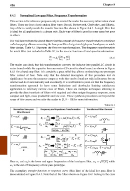
The reader can check that this transformation converts the inductor into parallel ℒ-circuit in
series branch while the capacitor becomes series ℒ-circuit in shunt brunch as shown in Figure
8.4.1 for a band-stop filter. It is certainly a great relief that allows synthesizing one prototype
filter instead of four. Note only that the detailed description of this procedure lost its
significance because the numerus computer tools that can be found not only in literature but on
internet and do it automatically and excellently. It is worthwhile to point out that the frequency
transformation approach do have some limitations and drawbacks limiting satisfactory
application to relatively narrow class of filters. There are multiple techniques allowing to
provide the direct synthesis of filters with required and often unique frequency response, more
compact and light, mass producible and low cost. These synthesis procedures are beyond the
scope of this course and we refer the reader to [3, 8 – 10] for more information.
Table 8.1
Here and is the lower and upper frequencies of the band-pass filter, = √ while
1 2 0 1 2
is the cut-off frequency of low-pass prototype.
The exemplary transfer function or response curve (blue line) of the ideal low-pass filter is
demonstrated in Figure 8.4.1. Note that all the filters shown in Figure 8.4.1 belong to the class