
Page 432 - Maxwell House
P. 432
412 Chapter 8
radiation. If so, the maximum peak leakage of power reaching the receiver should not generally
exceed 10 W and the protection level goes down to the realistic (80 – 100) dB. Evidently,
−2
any easing in transmitter power reduces the required protection level and makes simpler the
duplexer design.
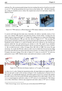
Figure 8.3.7 WR duplexer: a) Block diagram, b) WR balance duplexer, c) Active dual TR
tube
In systems with high and ultra-high power transmitter, the diplexer typically consists of two
main parts: balance WR duplexer and following diode or ferrite limiter. Consider first the
balance duplexer depicted in Figure 8.3.7b that is the combination of two short-slot WR hybrids
11
and dual Transmit-Receive (TR) gas tube like shown in Figure 8.3.7c . The incoming RF
power ionizes and leads to break down a gap between electrodes inside the tube. Evidently, the
breakdown power should be as small as possible and can be reduced by the lowering gas
pressure inside the tube and optimizing gas mixture as well. The speed of gas ionization
between electrodes and following breakdown may be increased by placing an active ignition,
i.e. the so-called keep-alive voltage of ranges from 100 volts to 1,000 volts across the gap
electrodes. As a result, the TR tube works as a short circuit at relatively lower power providing
practically total reflection during the transmitter pulse duration. According to data from the CPI
Company, the power leakage of the tube in Figure 8.3.7c does not exceed 10 W while the
−2
peak power is up to 1MW. Hybrids ensure some additional isolation in order of 20 dB.
Figure 8.3.8 WR short-slot balance duplexer: a) Tx regime, b) Rx regime
Let show how it works. During the transmission pulse, the input high power signal reaches the
first slot and splits in half (solid red lines in Figure 8.3.8a). Looking back in Section 8.2.6 of
this chapter, we could find the magnitude, and relative phase of all waves coming to the antenna
port after reflection from the ignited TR tube (upward diagonal fill on tube image). Finally, two
waves of equal magnitude and relative phase of 270° proceed to the antenna port. The leakage
waves (blue dotted lines) with the same magnitude and relative phase of 90° move to dummy
11 Public Domain Image, source: http://www.cpii.com/docs/datasheets/4/BTR218.pdf