
Page 433 - Maxwell House
P. 433
MORE COMPLICATED ELEMENTS OF FEED LINES 413
load and disperse there that provides additional receiver protection. Due to the imperfection of
hybrids and tubes, the desired magnitude and phase relations are slightly violated, and the tiny
portion of Tx power leaks to the receiver port. In general, the isolation between the transmitter
and receiver port might reach (60 – 100) dB in the passband 5% - 10% and frequency range up
to 90 GHz. During the silence time the tube is not activated (no upward diagonal fill on tube
image) and the signals from antenna pass freely (actually with some loss and reflection) through
the tube and combine in the port going to the receiver as Figure 8.3.8b demonstrates. Again,
the hybrids and tube are not perfect. In other words, a small portion of received signal is lost
dissipating in Tx port and dummy load.
Figure 8.3.7 illustrates only one of the possible implementations that may vary depending on
hybrid and tube type. Their obvious disadvantage is the physical size and weight. In general,
the receiver input circuits need higher protection level and might be provided by a combination
of Y-circulators (see Figure 6.8.7 in Chapter 6) and special ferrite or diode limiters [7]. Such
limiters are typically nonlinear devices controlled exclusively by input signal value or regulated
through the individual control unit. As we noted in Section 2.7 of Chapter 2, the spin precessing
in magnetized ferrites is an inharmonious phenomenon especially in the high level of
microwave H-field intensity comparable to bias. If so, this nonlinearity can be used deliberately
to absorb considerably large microwave signals exceeding some critical level. However, when
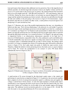
a rectangular pulse is transmitted through the gas tube or ferrite limiter, the leakage signal
waveform is no longer rectangular but consists of a leading edge spike followed by a plateau as
shown in Figure 8.3.9a. Such spike might ruin partly or wholly the input receiver circuit.
Therefore, behind the hybrid or ferrite protecting devices the diode active or passive limiters
can be found. We restrict our consideration to one example of active PIN diode limiter
schematically shown in Figure 8.3.9b [7].
Figure 8.3.9 Diode Limiter illustration: a) Typical waveform of transmitter and leakage pulse,
b) Block diagram of diode limiter circuitry
A small portion of Tx power diverged by the directional couple comes to the control unit
performing the same function as depicted in Figure 8.3.2. In particular, the operational amplifier
there compares the level of coming from transmitter signal to a reference one and supplies the
voltage or current bias to limiter diodes. As such, the input impedance of diodes drops almost
immediately to zero triggering the short circuit regime in the feed line linked to Rx port. Note
those active limiters are extremely fast (in the range of ns) and virtually suppress the leakage
edge spike. The additional receiver protection generally is in the range of (30 – 40) dB. We
refer the reader to the specialized literature [8, 9] for more information.