
Page 431 - Maxwell House
P. 431
MORE COMPLICATED ELEMENTS OF FEED LINES 411
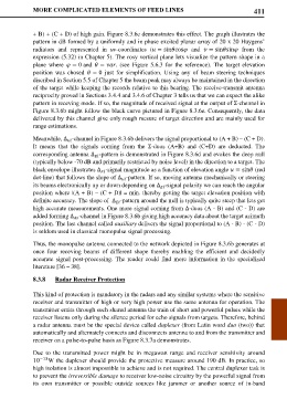
+ B) + (C + D) of high gain. Figure 8.3.6c demonstrates this effect. The graph illustrates the
pattern in dB formed by a uniformly and in phase excited planar array of 20 x 20 Huygens’
radiators and represented in uv-coordinates ( = sincos and = sinsin from the
expression (5.32) in Chapter 5). The rosy vertical plane lets visualize the pattern shape in a
plane where = 0 and = . (see Figure 5.6.3 for the reference). The target elevation
position was chosed = 0 just for simplification. Using any of beam steering techniques
discribed in Section 5.5 of Chapter 5 the beam peak may always be maintained in the direction
of the target while keeping the records relative to this bearing. The receive-transmit antenna
reciprocity proved in Sections 3.4.4 and 3.4.6 of Chapter 3 tells us that we can expect the alike
pattern in receving mode. If so, the magnitude of received signal at the output of Σ-chennel in
Figure 8.3.6b might follow the black curve pictured in Figure 8.3.6e. Consequently, the data
delivered by this channel give only rough mesure of target direction and are mainly used for
range estimations.
Meanwhile, ∆ -channel in Figure 8.3.6b delivers the signal proportional to (A + B) – (C + D).
It means that the signals coming from the Σ-duos (A+B) and (C+D) are deducted. The
corresponding antenna ∆ -pattern is demonstrated in Figure 8.3.6d and evokes the deep null
(typically below -70 dB and primarily restricted by noise level) in the direction to a target. The
black envelope illustrates ∆ -signal magnitude as a function of elevation angle = sin (red
dot-line) that follows the slope of ∆ -pattern. If so, moving antenna mechanically or steering
its beams electronically up or down depending on ∆ -signal polarity we can reach the angular
position where |(A + B) – (C + D)| = min. thereby getting the target elevation position with
definite accuracy. The slope of ∆ -pattern around the null is typically quite steep that lets get
high accurate measurements. One more signal coming from ∆-duos (A - B) and (C - D) are
added forming ∆ -channel in Figure 8.3.6b giving high accuracy data about the target azimuth
position. The last channel called auxiliary delivers the signal proportional to (A - B) - (C - D)
is seldom used in classical monopulse signal processing.
Thus, the monopulse antenna connected to the network depicted in Figure 8.3.6b generates at
once four receving beams of different shape thereby enabling the efficient and decidedly
accurate signal post-processing. The reader could find more information in the specialized
literature [36 – 38].
8.3.8 Radar Receiver Protection
This kind of protection is mandatory in the radars and any similar systems where the sensitive
receiver and transmitter of high or very high power use the same antenna for operation. The
transmitter emits through such shared antenna the train of short and powerful pulses while the
receiver listens only during the silence period for echo signals from targets. Therefore, behind
a radar antenna must be the special device called duplexer (from Latin word duo (two)) that
automatically and alternately connects and disconnects antenna to and from the transmitter and
receiver on a pulse-to-pulse basis as Figure 8.3.7a demonstrates.
Due to the transmitted power might be in megawatt range and receiver sensitivity around
−13 W the duplexer should provide the protective measure around 190 dB. In practice, so
10
high isolation is almost impossible to achieve and is not required. The central duplexer task is
to prevent the irreversible damage to receiver low-noise circuitry by the powerful signal from
its own transmitter or possible outside sources like jammer or another source of in-band