
Page 434 - Maxwell House
P. 434
414 Chapter 8
8.3.9 Frequency Multiplexer
In Chapter 6, we depicted how to assemble the Y-circulator and filter to get a frequency diplexer
merging two and more signals of different frequencies into one channel or separating them from
the common channel (see Figure 6.8.7e). The same task of multiplexing can be done using, for
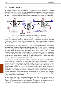
example, the quadrature hybrids as the schematic block diagram illustrates in Figure 8.3.10.
Figure 8.3.10 Schematic block diagram of frequency multiplexer
According to this chart, the diplexer consists of six hybrids and the same number of band-pass
filters. Each couple of identical filters pass signals concentrated around the particular
frequencies , , , or and reject, i.e. almost entirely reflects back outband frequencies.
1
4
3
2
The idealized frequency response of filters are shown in picture-in-pictures.
Let us first consider the signal of frequency coming to the left hybrid and freely passing
4
through the band-pass filters tuned to this signal. Looking back at Figure 8.3.4, we will find the
same way (simply replace amplifiers with filters) that the total power of this signal goes through
the bottom port of the second hybrid. Meanwhile, the top port of second hybrid stays highly
isolated. As such, we can inject through this port the additional signal of from independent
2
source. Since the filters are tuned to the different frequency, they block this signal reflecting it
backward. Looking back at Figure 8.3.8a, we see that reflected signal is combined with signal
of in the same common port of the second hybrid.
4
Evidently, the third in the sequence of diplexers accumulates the same way signals with the
center frequencies and in the right-size common port. Finally, two additional hybrids and
3
1
filters in the middle let accumulate the signals of and from two common ports into
2 4 1 3
one single channel . Note that the band-pass filters in this section of network are dual
1 2 3 4
banded passing the signal of and only while rejecting of and . In fact, the described
2
4
3
1
multiplexer is a reciprocal device and thus can not only combine many signals in the common
channel but also distribute the incoming multifrequency signal among many narrowband
channels. They found broad applications in broadcast, mobile, and satellite communication
systems allowing, for example, transmitting and receiving through the same antenna multiple
signals belonging to different services.
We have to stop here hoping that our short discussion is a good starting point for would-be
hybrid, multiplexer, and RF network designers. The application area of hybrids alone and in
combination with a wide variety of RF components is so broad that requires individual books
and courses. We refer the reader to the specialized literature [3, 8, 9, and 10].