
Page 430 - Maxwell House
P. 430
410 Chapter 8
(see Figure 5.5.1b in Chapter 5) namely Σ- beam and two Δ-beams (one for azimuth ∆ and
one for elevation ∆ tracking). To get such performance the elements of planar array like shown
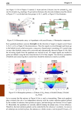
in Figure 5.7.1 are divided into four groups A, B, C, and D, as Figure 8.3.6a illustrates.
Figure 8.3.6 Monopulse array: a) 4 quadrants with pencil beams, c) Monopulse comparator
Each quadrant produces separate boresight (in the direction of target or targets) pencil beam
A, B, C, or D, as Figure 8.3.6a demonstrates. Then the signals received through each beam go
to the hybrid circuit called monopulse comparator (beamformer) consisting of 4 coaxial rings
(or any other) hybrids connected to a network and schematically shown in Figure 8.3.6b. Here
the incoming signals from the quadrants are marked in red. All output signals are marked in
green and defined using the data from Section 8.2.8 of this chapter. The electrical parameters
of hybrids and connecting them coaxial lines should be identical as much as possible.
c) d)
e) f)
Figure 8.3.6 Monopulse patterns: c) Σ-beam, d) ∆ -beam, e) Scaled Σ-beam, f) Scaled
∆ -beam
Let us assume that the antenna in Figure 8.3.6a is used as transmitting. Then each quadrant
plays evidently the role of an independent subarray with the curtain radiation pattern defined
by the number of radiators, their position in space, and feed design (see Section 5.6 in Chapter
5). Meanwhile, the quadrants are spatially shifted forming the planar array of four subarrays.
Therefore, the total radiation pattern can be controlled by the subarrays’ excitation. As soon as
all subarrays are excited in phase, the antenna as a whole creates a narrow pencil Σ-beam = (A