
Page 425 - Maxwell House
P. 425
MORE COMPLICATED ELEMENTS OF FEED LINES 405
isolation >20 dB with excellent balance in output phase ±1° and amplitude ±0.05 dB. The
insertion loss is typically bellow 0.2 – 0.5 dB depending on frequency range. The average
bandwidth is around an octave and up to 1:100, i.e. for example from 0.6 GHz to 36 GHz. Due
to skin effect, Ohmic loss in such broadband divider increases monotonically ~� and reaches
2 – 3 dB at high frequency end. Wilkinson dividers can be fabricated at any frequency subband
between 400 MHz and 100 GHz.
We stop here our consideration dedicated to directional couplers and hybrids referring the
reader to the specialized literature [3 - 5] and shift our attention to the more important issue, i.e.
their applications. It is almost impossible to imagine modern communication, radar or any other
RF system without directional couplers and hybrids. Here are some of the essential applications.
8.3 DIRECTIONAL COUPLER AND HYBRID APPLICATIONS
8.3.1 Signal Flow Measurements
It means the instantaneous and accurate measurement of RF signals various parameters like
power, magnitude, phase, frequency, waveform, etc. without interruption in service provided
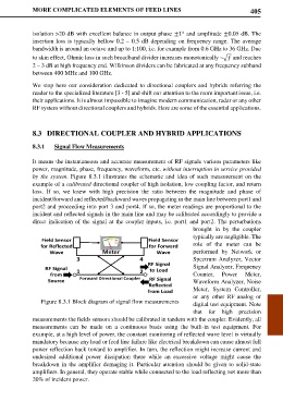
by the system. Figure 8.3.1 illustrates the schematic and idea of such measurement on the
example of a calibrated directional coupler of high isolation, low coupling factor, and return
loss. If so, we knew with high precision the ratio between the magnitude and phase of
incident/forward and reflected/backward waves propagating in the main line between port1 and
port2 and proceeding into port 3 and port4. If so, the meter readings are proportional to the
incident and reflected signals in the main line and may be calibrated accordingly to provide a
direct indication of the signal at the coupler inputs, i.e. port1 and port2. The perturbations
brought in by the coupler
typically are negligible. The
Field Sensor Field Sensor
for Reflected for Forward role of the meter can be
Wave Meter Wave performed by Network or
3 4 Spectrum Analyzer, Vector
RF Signal
RF Signal 1 2 to Load Signal Analyzer, Frequency
from Counter, Power Meter,
Source Forward Directional Coupler RF Signal Waveform Analyzer, Noise
Reflected
from Load Meter, System Controller,
Figure 8.3.1 Block diagram of signal flow measurements or any other RF analog or
digital test equipment. Note
that for high precision
measurements the fields sensors should be calibrated in tandem with the coupler. Evidently, all
measurements can be made on a continuous basis using the built-in test equipment. For
example, at a high level of power, the constant monitoring of reflected wave level is virtually
mandatory because any load or feed line failure like electrical breakdown can cause almost full
power reflection back toward to amplifier. In turn, the reflection might increase current and
undesired additional power dissipation there while an excessive voltage might cause the
breakdown in the amplifier demaging it. Particular attention should be given to solid-state
amplifiers. In general, they operate stable while connected to the load reflecting not more than
20% of incident power.