
Page 424 - Maxwell House
P. 424
404 Chapter 8
power proceeds into port4 with frequency independent phase shift −270°. Therefore, the EM
wave induced in port1 passes as a whole into port4 as long as a 3dB coupler keeps equal or
close to equal power division (see Figure 8.2.11e). Consequently, the quarter-wave section of
the 3dB coupler with two shorted ports is equivalent to three-quarter wavelength section of line
with frequency independent phase shift of −270°. Accordingly, the long section of line in
hybrid should be replaced with the quarter-wave section of the 3-dB coupler as Figure 8.2.11f
depicts. The passband jumps to 40% [3]. Note that the hybrid and directional coupler ports’
enumeration in Figure 8.2.11b is not related.
8.2.9 Wilkinson Power Divider
Microstrip variant of power divider proposed by E. Wilkinson in 1960 [4, 5] is widely used for
splitting RF power. It is incredibly simple, cheap in production and has excellent performance.
As any linear devices, it can be utilized in the reverse direction – as a power combiner.
According to the layout shown in Figure 8.2.12a, the trace of port1 split equally into two
symmetrically printed traces of arc shape.
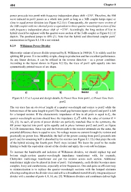
Figure 8.2.12 a) Layout and design details, b) Power flow from port1, c) Power flow from
port2.
The top trace has an electrical length of a quarter-wavelength and comes to port2 while the
bottom trace of the same length to port3.The small gap between inputs of port2 and port3 is left
for a lumped resistor. If the characteristic impedance of line in all ports is equal to , the
quarter-wavelength sections should have the impedance √2 while the value of resistor =
2 [3]. As such, all ports of power divider are perfectly matched. Due to the symmetry, the
RF power injected into port1 splits equally and in phase between port2 and port3, as Figure
8.2.12b demonstrates. Since top and the bottom path to the resistor terminals are the same, the
potential difference there is equal to zero. No voltage means no current through the resistor and
practically no power loss. Meanwhile, the half of the power coming from port2 proceeds into
port1 and the remaining half is absorbed by the resistor (see Figure 8.1.12c) that plays the role
of the hybrid missing the fourth port. Port3 stays isolated. We leave the proof to the reader
hinting to build the equivalent circuit of the divider and apply the even-odd technique.
To increase the bandwidth and isolation of Wilkinson dividers, we should replace top and
bottom single-section quarter-wavelength impedance transformer with, for example,
Chebyshev multi-stage transformer and put the resistor across each section. Additional
transformer might also be placed in front of port1. Unfortunately, such divider becomes more
complex, lossy and cumbersome, especially at low frequencies. One and quite an efficient way
to miniaturization is to replace the quarter-wavelength sections with the lumped elements
allowing scaling down the divider sizes and utilize a broadband monolithically integrated power
divider with a number of ports 4, 8, 16, etc. [3]. Wilkinson dividers and combiners deliver high