
Page 427 - Maxwell House
P. 427
MORE COMPLICATED ELEMENTS OF FEED LINES 407
between the generator and the end load like an antenna. The simplified block diagram of such
automatic external power-leveling unit is shown in Figure 8.3.2. The signal from the RF
detector is digitized inside the control unit. Then an operational amplifier in it compares the
level of this signal to a reference one and delivers the voltage or current controlling the RF
attenuator in such a manner as to keep the sampled and reference signal the same. The variable
set-resistor lets regulate the control unit dynamic range and avoid the instability inherent in the
system with feedback. Additionally, the control unit performance can be adjusted through the
external input.
8.3.4 Distributed Antenna System (DAS)
This system is defined as a network of spatially separated antennas connected to each other and
the so-called head-end station through the in-building fiber-optic and coaxial distribution
system. The drive for such network is to provide reliable wireless data, voice, public safety and
security communications inside the office and residential buildings, hotels, hospitals, schools,
university campuses, factories, stadiums, and other facilities where the building structure, large
concentration of people or other obstacles compromise the wireless signal propagation. Figure
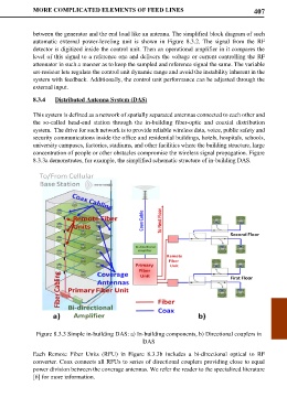
8.3.3a demonstrates, for example, the simplified schematic structure of in-building DAS.
Figure 8.3.3 Simple in-building DAS: a) In-building components, b) Directional couplers in
DAS
Each Remote Fiber Units (RFU) in Figure 8.3.3b includes a bi-directional optical to RF
converter. Coax connects all RFUs to series of directional couplers providing close to equal
power division between the coverage antennas. We refer the reader to the specialized literature
[6] for more information.