
Page 423 - Maxwell House
P. 423
MORE COMPLICATED ELEMENTS OF FEED LINES 403
1. Extend the operation frequency band up to 40% [3].
2. Miniaturize the device replacing the parts of the ring with a combination of lumped
inductances and capacitances.
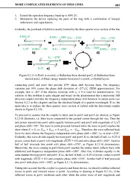
Evidently, the passband of hybrid is mostly limited by the three-quarter wave section of the line
Figure 8.2.11 b) Port1 is excited, c) Reflection from shorted port3, d) Reflection from
shorted port2, d) Final energy transfer from port1 to port4, e) Hybrid layout
connecting port2 and port4 that provide 270° phase shift between them. The frequency
variation just 10% causes the phase shift deviation of ~27° √ (TEM approximation). For
example, that is ~81° if the alumina substrate with = 9 is used for miniaturization. The
solution of this problem is quite elegant and based on the phenomenon that a microstrip 3dB
direction coupler provides the frequency independent phase shift between its output ports (see
Section 8.2.3 in this chapter) and has the electrical length of a quarter-wavelength. If so, the
main idea is to replace the three-quarter wave section of hybrid with the directional coupler
shown in Figure 8.2.11b.
To proceed let assume that the coupler is ideal, and its port2 and port3 are shorted, as Figure
8.2.11b illustrates, i.e. their traces connected to the ground screen through the vias. Then the
unit power injected into port1 splits equally between port2 and port3 with magnitude of 1/√2
and phase shift −90°. The wave in port4 proceeds forward while the wave in port2 reaches the
short where = 0, i.e. + = 0 and = − . Therefore, the wave reflected back
from the short obtains the frequency independent extra phase shift −180°, i.e. in total −270°.
Evidently, this wave divides equally between port1 and port4. If so, the half of half, i.e. 0.25 of
power, comes back to port1 with magnitude √0.25 = 0.5 and entire phase shift−360°. Another
half of half proceeds into port4 with phase shift −270°, as Figure 8.2.11d demonstrates.
Meanwhile, the wave coming in port3 from port1 reaches the similar short, reflects back with
additional and frequency independent phase shift −180°. After that, it divides equally in the
same manner between port1 and port4. If so, the half of half, i.e. 0.25 of power, comes to port4
with magnitude √0.25 = 0.5 and complete phase shift −270°. Another half of half proceeds
into port1 with phase shift −180°, as Figure 8.2.11c demonstrates.
Taking into account that the coupler is a passive and linear device, we should combine reflected
waves in port1 and forward waves in port4. According to drawing in Figure 8.2.11c, d the
reflected waves in port1 annihilate each other while the entire wave of unit magnitude and