
Page 420 - Maxwell House
P. 420
400 Chapter 8
flow behaves literally like a river splitting into two separate streams. Figure 8.2.8e exhibits
the frequency dependence of S-matrix parameters. All terms in this figure are expressed in
decibels.
We conclude here our WR hybrid deliberation due to lack of space hoping that the reader can
get additional information from the specialized literature [8].
8.2.7 Microstrip Branch Hybrid
The layout of a customarily called branch or branch-line microstrip hybrid is illustrated in
Figure 8.2.9a . The characteristic impedance of all input ports as well as the two vertical stubs
6
(branches) AC and BD are equal to , typically 50 or 75 Ω, and defined by the dielectric
constant of microstrip substrate and trace width. The impedance of line AB and CD will be
chosen in the process of later study. Before undertaking an analysis, note that the existence of
symmetry plane as shown in Figure 8.2.9a and b makes possible to apply again the method
1 2
of even- and odd-mode excitation. As usual, this technique is based on two principles:
symmetry of the device and superposition. Assuming that the energy of quisi-TEM mode in
microstrip of unit magnitude ( = 1) is injected into the port1 while port3 ( = 0) is not
1
3
excited (see Figure 8.2.9b), we proceeds in several steps.
1. Following the even- and odd-mode idea, we can represent = 1 = 05 + 0.5 and =
3
1
0.5 + (−0.5) and consider two excitation cases illustrated in Figure 8.2.9b.
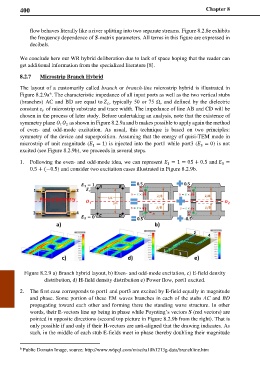
Figure 8.2.9 a) Branch hybrid layout, b) Even- and odd-mode excitation, c) E-field density
distribution, d) H-field density distribution e) Power flow, port1 excited.
2. The first case corresponds to port1 and port3 are excited by E-field equally in magnitude
and phase. Some portion of these EM waves branches in each of the stubs AC and BD
propagating toward each other and forming there the standing wave structure. In other
words, their E-vectors line up being in phase while Poynting’s vectors S (red vectors) are
pointed in opposite directions (second top picture in Figure 8.2.9b from the right). That is
only possible if and only if their H-vectors are anti-aligned that the drawing indicates. As
such, in the middle of each stub E-fields meet in phase thereby doubling their magnitude
6 Public Domain Image, source: http://www.w6pql.com/misc/ra18h1213g-data/branchline.htm