
Page 417 - Maxwell House
P. 417
MORE COMPLICATED ELEMENTS OF FEED LINES 397
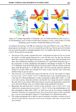
Figure 8.2.7 E-plane ring hybrid: a) Schematic view, b) E-field distribution, port1 excited, c)
H-field distribution, port1 excited, d) Power flow (Poynting’s vector), port4 excited, e) E-field
distribution, port4 excited, f) H-field distribution, port4 excited.
According to the drawing, four WR are connected to the same WR bent into a ring. WRs are
placed quarter wavelength, i.e. Λ 4, over around the top of the ring. The red sports on the dotted
⁄
red circle mark the quarter wavelength separation. If so, the length of the bottom section of ring
is 3Λ 4. We proceed in several steps.
⁄
1. The energy of TE10-mode is injected into port1. Looking back at Figure 8.2.6a, we see that
this mode is divided equally between two waves: the first runs over the ring clockwise
while the second one in the opposite direction, i.e. counterclockwise. Moving towards each
other, they establish the standing wave distribution of E- and H-fields along the ring, i.e.
the consequence of nodes (minimums) and antinodes (maximums) as Figures 8.2.7b and
8.2.7c illustrates. Note that E-field node has the level around -5 dB only (relative to the red
peak) while H-field drops to -25 dB (dark blue). We know that the antinodes should be
situated at all spots where two running waves meet in phase and the nodes where they
interfere being in opposite phase.
2. The clockwise wave reaching port2 passes the pathway over the ring equals (see Figure
8.2.7a) to Λ 4 + Λ 4 + 3 Λ 4 = Λ 4 + Λ while the track of the counterclockwise wave
⁄
⁄
⁄
⁄
is the only Λ/4. The path difference is Λ that corresponds to phase shift of 360°, i.e. both
waves join in phase, create the maximum and transfer their energy into port2. Evidently,
the same effect occurs at port3. The ring symmetry securities the equal energy transfer into
port3 and port4. Besides, they are excited in phase being equidistant from port1.
3. Meanwhile, the path from port1 to port4 for the clockwise wave is Λ 4 + Λ 4 = Λ 2
⁄
⁄
⁄
⁄
⁄
⁄
while for the counterclockwise wave is Λ 4 + 3 Λ 4 = Λ. If so, the path difference is Λ 2
that corresponds to phase shift of 180°, i.e. both waves join in out-of-phase creating the
minimum. Therefore, the energy from port1 does not proceed in port4 at all or generally
has a very low level (dark blue). Figure 8.2.7b and Figure 8.2.7c illustrate this effect.
4. The reciprocal principle tells us that the equal in magnitude and phase excitation of port2
and port3 means that the energy proceeds to port1 customary called sum- or Σ-port. Port4
stays isolated.