
Page 418 - Maxwell House
P. 418
398 Chapter 8
5. Now, let us inject the energy of TE10-mode into port4, as shown in Figure 8.2.7d - f.
Following in much the same way, we can find that the incoming energy is divided equally
between port3 and port4 again while the signals in these ports are out-of-phase (180°).
Port4 and port1 do not communicate to each other. Therefore, the equal in magnitude and
opposite phase excitation of port2 and port3 means that the energy proceeds to port4
customary called different- or Δ-port. Port1 stays isolated.
6. Figure 8.2.7d demonstrates the active part of Poynting’s vector, i.e. the direction and
density of active power flow in the ring hybrid. It is clear that all EM energy accumulated
nearby port1 is reactive by nature.
7. Since the operation principle of a ring hybrid is based on the interference of waves passing
different distances over the ring, practically all its parameters (especially isolation between
ports) are quite sensitive to frequency deviations. That is why the ring hybrids are in class
of narrow banded, i.e. ±(5 − 10)%, devices.
The significant advantage of WR ring hybrids is a very low Ohmic loss that makes them
applicable up to 100 - 150 GHz and high power handling.
8.2.6 WR Short-Slot Hybrid (Riblet Hybrid)
H. J. Riblet proposed this type of WR forward hybrid in 1952. The commonly used H-plane
modification called sidewall is shown in Figure 8.2.8a. The hybrid is comprised of two WR
side by side with a portion of the common narrow wall removed as Figure 8.8.8b demonstrates.
It can survive extremely high power practically limited only by the breakdown in the feeding
WR. Due to the simple design and cheap fabrication, compact size and low loss, it found broad
applications at frequencies up to 100 – 150 GHz. Properly optimized hybrid provides the
coupling = 3 ± 0.125 dB and isolation I above 30 dB in passband around 15%. The lower
frequency limit is nearby 3 GHz and determined by the hybrid size and weight.
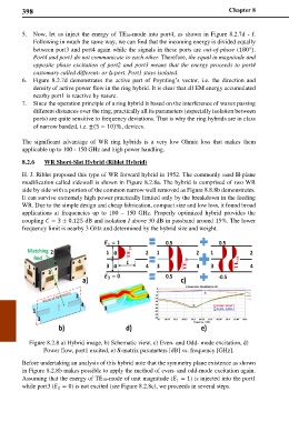
Figure 8.2.8 a) Hybrid image, b) Schematic view, c) Even- and Odd- mode excitation, d)
Power flow, port1 excited, e) S-matrix parameters [dB] vs. frequency [GHz].
Before undertaking an analysis of this hybrid note that the symmetry plane existence as shown
in Figure 8.2.8b makes possible to apply the method of even- and odd-mode excitation again.
Assuming that the energy of TE10-mode of unit magnitude ( = 1) is injected into the port1
1
while port3 ( = 0) is not excited (see Figure 8.2.8c), we proceeds in several steps.
3