
Page 416 - Maxwell House
P. 416
396 Chapter 8
magnitude advances into port4 keeping port1 isolated. That is why port1 is customarily called
the sum port or Σ-port while port4 is named the different port or Δ-port. Note the complete
analogy with balanced null detector bridges used for impedance measurements.
In the course of our consideration, we omitted such essential part of the magic-T performance
as matching. Look back at Figure 8.2.5c where the solid yellow lines illustrate schematically
how the longitudinal current on WR top broad wall is divided into two equal parts before
proceeding into port2 and port3. From the circuit theory, we know that such current split takes
place if two equal impedances are connected in parallel. Loosely speaking, the same should be
correct for WRs if we neglect the reactive fields of high modes existing in the area between
WRs. In other words, port1 with impedance is connected to two WRs of the same
impedance in parallel, i.e. the loaded impedance for port1 is approximately /2. If so, we
should expect the return loss around -10 dB (~10% of incident power) that often is not suitable.
Around the same level of reflections accompanies the port4 excitation. The only difference that
WR in port4 is loaded on the impedance around 2 . To reaffirm this let turn to the current
structure on the WR broad walls, shown schematically in Figure 8.2.6b (yellow lines). The
current on the left side of broad wall of port4 goes down, turns left and continues its movement
along the top wall of WR in port2. Then it follows down as the displacement current (red
vector), reaches the bottom wall of WR in port2, and runs straight to the port 3. Here this current
jumps up as the displacement current and returns to the port 4. Therefore, the impedances of
port2 and port3 connected to port4 in series thereby doubling the load impedance. Figure 8.2.6c
demonstrates one of the possible approach to match using the cone-probe structure. The probe
diameter and its length are selected in such a way that the waves reflected from the probe and
WR narrow wall behind the probe cancel each other. If so, the separation between probe and
wall should be around a quarter wavelength. Meanwhile, the base cone provides the smooth
transition from port4 to port2 and port3. The thorough numerical optimization lets develop the
magic-T with return loss below -15 dB over 90% of single mode WR bandwidth. Theoretically,
the magic tees could be design at any frequency, but they become too bulky and heavy at
frequencies bellow 3 GHz and too difficult to fabricate above 180 GHz. Finally, we can write
the S-matrix of fully matched and lossless magic-T as
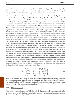
⁄
0 1 √2 1 √2 0
⁄
⎛ 1 √2 0 ⎞
⁄
⁄
= 0 −1 √2 (8.6)
⎜ ⎟
1 √2 0 0 1 √2
⁄
⁄
⁄
⁄
⎝ 0 −1 √2 1 √2 0 ⎠
We offer the reader to check using the even- and odd-mode approach that the energy from port2
is divided equally and in opposite phase between port1 and port4 while port3 stays isolated. It
looks quite surprising why an EM wave from port2 prefers to turn up and right instead of going
straight to port3. Try to explain this phenomenon.
8.2.5 WR Ring Hybrid
There are two main modifications of WR ring hybrid: H-plane and in E-plane ring also is called
rat-race coupler. We will limit our consideration to slightly more straightforward and compact
E-plane hybrid shown in Figure 8.2.7a.