
Page 421 - Maxwell House
P. 421
MORE COMPLICATED ELEMENTS OF FEED LINES 401
while H-fields drops to zero in the same cross section. If so, we can cut the hybrid into two
identical and independent parts as shown in Figure 8.2.9b. Each part consists of the straight
line connecting the opposite ports, and the two parallel stubs of /8 length opened at the
end. Keep in mind that the mentioned wavelength should be calculated as /� ,
where < , to take into account that the relatively small but finite portion EM wave
in microstrip propagates out of substrate in free space (see Figure 6.6.16 in Chapter 6).
3. Just in the similar manner, we can demonstrate that the hybrid in the case of odd-mode
excitation should be split again into two identical and independent halves as shown in
Figure 8.2.9b (last top drawing on the right). In particular, along the symmetry line
1 2
H-fields meet in phase thereby doubling their magnitude while E-field drops to zero being
anti-aligned. Each half consists of the straight line connecting the opposite ports and
parallel stubs of /8 length shorted at the end.
4. Strait comparison between each elementary half in Figure 8.2.9b and an in-line resonator
in Figure 8.1.1a reveals their actual equivalency. Now the role of discontinuities performs
open-ended or short-ended half-length stubs. Therefore, our task should be to choose the
value of characteristic impedance = of microstrip between stubs in such manner
that all energy passes through each half without reflection. Using this fact, i.e. assuming
| | = 1 in the expression of Figure 8.1.1d, and knowing that 2 = /2 at the central
2
frequency, we can find and finally the impedance we are looking for. It should be =
11
= /√2.
5. The CST model we have developed illustrates E-field (Figure 8.2.9c) and H-field (Figure
8.2.9d) distribution over the hybrid at the central frequency 2.8687 GHz while Figure
8.2.9e demonstrates the active power flow through the hybrid. The comparison reveals
quite intensive reactive E- and H-fields accumulated in stubs as it were expected and in the
microstrip CD connected to the isolated port3.
Let us review the main results.
1. The brunch hybrid belongs to the class of the forward 3-dB directional coupler.
2. The physical and electrical path from port1 to port4 is longer by a quarter-wavelength than
from the port1 to port2. As a result, the wave coming to port 4 receives an additional phase
shift (−90°) relative to wave in port2. Therefore, the branch hybrid can be classified as a
quadrature 3-dB coupler.
3. Due to all hybrid components are selected in accordance with the wavelength the hybrid
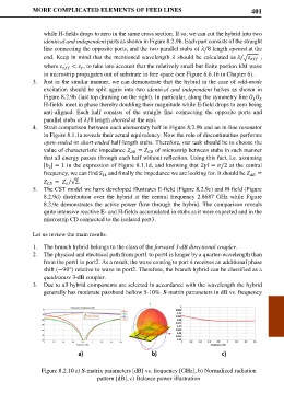
generally has moderate passband bellow 5-10%. S-matrix parameters in dB vs. frequency
a) b) c)
Figure 8.2.10 a) S-matrix parameters [dB] vs. frequency [GHz], b) Normalized radiation
pattern [dB], c) Balance power illustration